FAIRCHILD FSUSB30 handbook
Contents
1. FSUSB30 Rev 1 1 6 3 DC Electrical Characteristics All typical values are at 25 C unless otherwise specified TA 40 C to 85 C Symbol Parameter Conditions Vec V Unit Min Typ Max Vik Clamp Diode Voltage lin 18mA 3 0 1 2 V 3 0 to3 6 1 3 V ViH nput Voltage HIGH 43 1 7 V 3 0 to 3 6 0 5 V VIL Input Voltage LOW 4 3 0 7 V lin Control Input Leakage Vsw 0 0V to Vcc 4 3 1 0 1 0 HA loz OFF State Leakage 0 lt Dn HSD1 HSD2 lt Vee 43 2 0 2 0 HA Povver OFF Leakage a m oFF Current D D Vsw OV to 4 3V Vec 0V 0 2 0 2 0 HA Vow 0 4V lon 6mA 3 0 6 5 10 0 Q Ron Switch On Resistance SW ON Vsw OV lo 30mA at 25 C 3 6 7 0 Q ARon Delta Ron 4 Vew 0 4V loy 8mA 3 0 0 35 Q Ron Flatness Ron Flatness3 Vsw 277 3 0 2 0 Q lon 8mA loc Quiescent Supply Current cane UOV eren 4 3 1 0 HA OUT Increase in Icc Current z lect per Control Voltage Ventre control input 2 6V 4 3 10 0 pA Notes 3 Measured by the voltage drop between Dn HSD1 HSD2 pins at the indicated current through the switch On resistance is determined by the lower of the voltage on the two ports 4 Guaranteed by characterization AC Electrical Characteristics All typical values are for Vcc 3 3V at 25 C unless otherwise specified TA 40 C to 85 C i Symbol Parameter Conditions Vec2. 1 1 6 18 www fairchildsemi com uo uus Sdqwosr 0 2 ASN p ds uBH HOod OM 4 MO A4071 068SnS4
3. TA 40 C to 85 C i Symbol Parameter Conditions Units ToS Min Typ Max umber Cin Control Pin Input Capacitance Vec 0V 1 5 pF Figure 16 Con D1 D2 Dn On Capacitance Vece 3 3 OE OV 3 7 pF Figure 15 Copp D1 D2 Off Capacitance Vcc and OE 3 3 2 5 pF Figure 16 2006 Fairchild Semiconductor Corporation FSUSB30 Rev 1 1 6 www fairchildsemi com YoIMS sdq yogr 0 ASN p ds uBH 3 4044 OAAL mod M07 OEASNSA Typical Characteristics Frequency Response Gain dB k 10 100 1000 10000 Frequency MHz CL OpF Vcc 3 3V Figure 2 Gain vs Frequency Frequency Response Off Isolation dB 10 100 1000 Frequency MHz Figure 3 Off Isolation Frequency Response Crosstalk dB 10 100 1000 Frequency MHz Voc 3 3V Figure 4 Crosstalk 2006 Fairchild Semiconductor Corporation FSUSB30 Rev 1 1 6 www fairchildsemi com YoIMS SdqWOsr 0 Z ASN p ds uBH 40g OML MOdg MO7 DEASNSSA Test Diagrams Ron Von lon Figure 5 On Resistance R Rs and C are functions of the application
4. V Unit Figure Min Typ Max Number Turn On Time S HD1 HD2 0 8V ton OE to Output R 500 C 5pF 3 0 to 3 6 13 30 ns Figure 9 Turn Off Time S HD1 HD2 0 8V torr OE to Output R 500 C 5pF 3 0 to 3 6 12 25 ns Figure 9 4 G Figure 7 tpp Propagation Delay R 509 C 5pF 3 3 0 25 ns Figure 8 teem Break Before Make 2057 3 0 to 3 6 2 0 6 5 ns Figure 10 Vin 0 8V Off Isolation E z a OIRR Non Adjacent f 240MHz Rz 509 3 0 to 3 6 30 dB Figure 13 Xtalk Non Adlacent Channel R 500 f 240MHz 3 01036 45 dB Figure 14 Crosstalk R7 500 C OpF 720 BW 3dB Bandwidth 3 0 to 3 6 MHz Figure 12 Rr 500 Cq 5pF 550 2006 Fairchild Semiconductor Corporation FSUSB30 Rev 1 1 6 www fairchildsemi com YoIMS SdqWOsr 0 2 ASN p ds uBH 3 4044 OAAL aMOdg MO 068SnS4 USB Hi Speed Related AC Electrical Characteristics TA 40 C to 85 C Figure Symbol Parameter Conditions Vec V Units Min Typ Max Number Channel to Channel _ _ Figure 7 sk o Skevv5 RL 500 CL 5pF 3 0 to 3 6 50 ps Figure 11 Skew of Opposite Figure 7 tsx p Transitions of the R 509 C 5pF 3 0 to 3 6 20 ps Fi 7 1 Same Output g RL 500 CL 5pF ty Total Jitter tr te 500ps at 480 Mbps 3 0 to 3 6 200 ps PRBS 215 1 Note 5 Guaranteed by characterization Capacitance
5. specifications do not expand the terms of Fairchild s worldwide terms and conditions specif ically the warranty therein which covers Fairchild products Always visit Fairchild Semiconductor s online packaging area for the most recent package drawings http uvvvvv fairchildsemi com packaging O 2006 Fairchild Semiconductor Corporation www fairchildsemi com FSUSB30 Rev 1 1 6 17 YdIMS sdq yogr 0 ASN p ds uBH 40g OML aMOdg MO7 OEASNSSA Ee aa mil FAIRCHILD ae eae SEMICONDUCTOR TRADEMARKS intended to be an exhaustive list of all Build it Now CorePLUS CorePOVVER CROSSVOLT CTLTM Current Transfer Lagic EcoSPARK EfficentMax EZSWITCH EZ Fairchild Fairchild Semiconductor FACT Quiet Series FACT FAST FastvCore FlashV Vriter FPS DISCLAIMER LIFE SUPPORT POLICY As used herein ANTI COUNTERFEI TING POLICY under Sales Support Definition of Terms such trademarks F PFS FRFET Global Power Resource Green FPS Green FPS e Series GTo IntelliMAX ISOPLANAR MegaBuck MICROCOUPLER MicroFET MicroPak MillerDrive MotionMax Motion SPM OPTOLOGIC OPTOPLANAR e PDP M TM PowerSPM 1 Life support devices or systems are devices or systems which a are intended for surgical implant into the body or b support or sustain life and c whose failure to perform when prope
6. 006 Fairchild Semiconductor Corporation www fairchildsemi com FSUSB30 Rev 1 1 6 14 4 00 MAX Ru LIL 0 50 TYP 1 10 24 TYP m8 ECOMMENDED LAND PATTERN Physical Dimensions i 3 00 p Bi 0 50 1 50 A x O 0 15 c l xlalos e TOP VIEW 0 80 MAX 0 10 C 0 20 tho L A o o8 c hf 84 SNS SIDE VIEW 1 65 MAX H 030 PIN 1 IDENT xO i i f wets qai 18 l paing ag L E aa js 0 10 C A B Mrl BOTTOM VIEW NOTES A CONFORMS TO JEDEC REGISTRATION MO 241 VARIATION AA B DIMENSIONS ARE IN MILLIMETERS C DIMENSIONS AND TOLERANCES PER ASME Y14 5M 1994 MLP14ArevA warranty therein which covers Fairchild products Always visit Fairchild Semiconductor s online packaging area for the most recent package drawings http www fairchildsemi com packaging Figure 18 14 Terminal De populated Quad Very Thin Flat Pack No Leads DQFN JEDEC MO 241 2 5 x 3 0mm Package drawings are provided as a service to customers considering Fairchild components Drawings may change in any manner with out notice Please note the revision and or date on the drawing and contact a Fairchild Sem
7. 59 0 512 0 795 7 008 0 488 0 724 12mm 330 1 50 13 00 20 20 178 12 4 18 4 2006 Fairchild Semiconductor Corporation FSUSB30 Rev 1 1 6 12 www fairchildsemi com YoIMS sdq yogr 0 ASN p ds uBH 10g OML aMOdg MO 068SnS4 Tape Dimensions for MSOP 0 30 0 05 P2 2 0 0 1 2 Dimensions are in inches millimeters unless otherwise specified Po 4 0 0 1 3 201 5540 05 x E 1 754 O0 1 rar 61 604 0 1 a nan E ele m T fil K1 R 0 5 TYPICAL x o SECTION X X sipi Ao REF 3 3 0 1 Ac 5 30 0 1 Bo 3 30 0 1 REF O 30 Ba 1 1303201 REF O 3 Ko K1 1 00 0 1 t F 5 50 0 1 P1 8 00 0 1 REF 0 4 W 12 00 0 3 SECTION Y Y Notes 1 All dimensions are in millimeters 2 Measured from centerline of sprocket hole to centerline of pocket 3 Cumulative tolerance of ten sprocket holes is 0 20mm 4 Other material available Reel Dimensions for MSOP Dimensions are in inches millimeters unless otherwise specified 7 ES Wi A TAPE SLOT A N DETAIL X k Wz SCALE 3X e Ww Tape Size A B Cc D N VV1 W2 W3 13 0 059 0 512 0 795 7 008 0 448 0 724 0 468 0 606 12mm 330 1 5 13 20 2 178 12 4 18 4 1 11 9 15 4 2006 Fairchild Semiconductor Corporation FSUSB30 Re
8. Click to see this datasheet in Simplified Chinesel SS FAIRCHILD SESS SEMICONDUCTOR FSUSB30 Switch Features m Low On Capacitance 3 7pF Typical m Low On Resistance 6 5Q Typical m Low Power Consumption 1A Maximum 10HA Maximum cr over an Expanded Control Voltage Range Vix 2 6V Vcc 4 3V Wide 3dB Bandwidth gt 720MHz 8KV ESD Protection m Power Off Protection when Vcc OV D D Pins can Tolerate up to 5 5V m Packaged in 10 lead MicroPak 1 6 x 2 1mm 14 lead DQFN 10 lead MSOP 10 lead UMLP 1 4 x 1 8mm Applications m Cell phone PDA Digital Camera and Notebook LCD Monitor TV and Set top Box Related Application Notes m AN 6022 Using the FSUSB30 FSUSB31 to Comply with USB 2 0 Fault Condition Requirements September 2008 Lovv Povver Tvvo Port High Speed USB 2 0 480Mbps Description The FSUSB30 is a low power two port high speed USB 2 0 switch Configured as a double pole double throw DPDT switch it is optimized for switching between two high speed 480Mbps sources or a Hi Speed and Full Speed 12Mbps source The FSUSB30 is compatible with the requirements of USB2 0 and features an extremely low on capacitance Con of 3 7pF The wide bandwidth of this device 720MHz exceeds the band width needed to pass the third harmonic resulting in sig nals with minimum edge and phase distortion Superior channel to channel crosstalk minimizes interfe
9. EIN WHICH COVERS THESE PRODUCTS FAIRCHILD S PRODUCTS ARE NOT AUTHORIZED FOR USE AS CRITICAL COMPONENTS IN LIFE SUPPORT DEVICES OR SYSTEMS WITHOUT THE EXPRESS WRITTEN APPROVAL OF FAIRCHILD SEMICONDUCTOR CORPORATION 2 A critical component in any component of a life support device or system whose failure to perform can be reasonably expected to cause the failure of the life support device or system or to affect its Fairchild Semiconductor Corporation s Anti Counterfeiting Policy Fairchildis Ant Counterfeiting Policy is also stated on our external website www fairchildsemi com Counterfeiting of semiconductor parts is a growing problem in the industry All manufacturers of semiconductor products are experiencing counterfeiting of their parts Customers who inadvertently purchase counterfeit parts experience many problems such as loss of brand reputation substandard performance failed applications and increased cost of production and manufacturing delays Fairchild is taking strong measures to protect ourselves and our customers from the proliferation of counterfeit parts Fairchild strongly encourages customers to purchase Fairchild parts either directly from Fairchild or from Authorized Fairchild Distributors who are listed by country on our web page cited above Products customers buy either from Fairchild directly or from Authorized Fairchild Distributors are genuine parts have full traceability meet F airchild s quality standards for handlin
10. HLi pHt O 2006 Fairchild Semiconductor Corporation FSUSB30 Rev 1 1 6 www fairchildsemi com YOIMS SdqWOsr 0 Z ASN p ds uBH 40g OML aMOdg MO7 DEASNSSA Netvvork Analyzer FSUSB30 OFF Isolation 20 Log Vour Vn Figure 13 Channel Off Isolation Netvvork Analyzer V GND Rs and Ry are functions of the application environment 50 75 or 1002 Crosstalk 20 Log Vour Vin Figure 14 Non Adiacent Channel to Channel Crosstalk Capacitance Meter Capacitance f 240MHz Vse 0 or Voc Meter YoIMS SdqWOsr 0 Z ASN p ds uBH 40g OML MOdg MO7 DEASNSSA Din D2n f 240MHz Figure 15 Channel On Capacitance Figure 16 Channel Off Capacitance 2006 Fairchild Semiconductor Corporation www fairchildsemi com FSUSB30 Rev 1 1 6 9 Application Guidance Meeting USB 2 0 Vbus Short Requirements n section 7 1 1 of the USB 2 0 specification it notes that USB devices must be able to vvithstand a Vbus short to D or D when the USB devices is either powered off or powered on The FSUSB30 can be successfully config ured to meet both these requirements Power Off Protection For a Vbus short circuit the switch is expected to with stand such a condition for at least 24 hours The FSUSB30 has specially designed circuitry which pre vents unintended signal bleed through as well as guar anteed system reliability during a power down
11. child Semiconductor Corporation O 2006 Fairchild Semiconductor Corporation FSUSB30 Rev 1 1 6 www fairchildsemi com YoIMS sdq yogr 0 ASN p ds uBH 10g OML aMOdg MO 068SnS4 Connection Diagrams Pad Assignments for MicroPak E HSD1 HSD2 GND Vcc Top View Pad Assignments for DQFN Top Through View Pin Assignment for MSOP Top Through View Pad Assignments for uMLP HSD1 o HSD2 Vcc 3 4 GND o 2 3 HSD1 gt 5 U HSD2 Top Through View Analog Symbol HSD1 y HSD2 4 HSD1 y HSD2 3 57 es OE ontro Pin Descriptions Pin Name Description OE Bus Switch Enable S Select Input D D HSDn HSDn Data Ports NC No Connect Truth Table S OE Function X HIGH Disconnect LOVV LOVV D D HSD1 HIGH LOW D D HSD2 2006 Fairchild Semiconductor Corporation FSUSB30 Rev 1 1 6 www fairchildsemi com YoIMS SdqWOsr 0 2 ASN p ds uBH 40g OML aMOdg MO7 068SnS4 Absolute Maximum Ratings Stresses exceeding the absolute maximum ratings may damage the device The device may not function or be opera ble above the recommended operating conditions and stressing the parts to these levels is not recommended In addi tion extended exposure to stresses above the recommended o
12. environment see AC Electrical tables for specific values C includes test fixture and stray capacitance Figure 7 AC Test Circuit Load NC L Vin Ven Each switch port is tested separately Figure 6 Off Leakage trise 500ps teat 500ps 800mV L Input HSDn HSDn 400mV Output D D Figure 8 Switch Propagation Delay Waveforms RISE 2 5ns GND Output s Vout VoL tral 2 5ns ton Figure 9 Turn On Turn Off Waveform 2006 Fairchild Semiconductor Corporation FSUSB30 Rev 1 1 6 www fairchildsemi com YoIMS sdq yogr 0 ASN p ds uBH 3 4044 OAAL AMOdg MO DEASNSSA Control nput P Control 50 Input D C includes test fixture and stray capacitance Figure 10 Break Before Make team R t 2 5ns 10 90 0 9 x Vout RISE 500ps 400mV trise 500ps 800mV Input HSDn HSDn 400mV 90 Output D D VoL pLH Tskp teu teu Pulse Skew Tsp Rs and R are functions of the application environment See AC Electrical Tables for specific values Output1 HSD1 HSD1 VoL ke F Output1 D2 D2 VoL tpLH2 gt ttan 500ps pHLo pHL Tsk o tpLH1 PLH or Output Skew Tsk ouT Figure 11 Switch Skew Tests Network Analyzer Figure 12 Bandwidth p
13. g and storage and provide access to Fairchild s full range of up to date technical and product information Fairchild and our Authorized Distributors will stand behind all warranties and will appropriately address any warranty issues that may arise Fairchild will not provide any warranty coverage or other assistance for parts bought from Unauthorized Sources Fairchild is committed to combat this global problem and encourage our customers to do their part in stopping this practice by buying direct or from authorized distributors Datasheet Identification Product Status Definition Advance Information Formative In Design Datasheet contains the design specifications for product development Specifications may change in any manner without notice Preliminary No Identification Needed Full P Obsolete First Production Not In Production Datasheet contains preliminary data supplementary data will be published at a later date Fairchild Semiconductor reserves the right to make changes at any time without notice to improve design roduction Datasheet contains final specifications Fairchild Semiconductor reserves the right to make changes at any time without notice to improve the design Datasheet contains specifications an a product that is discontinued by Fairchild Semiconductor The datasheet is for reference information only Rey 136 2006 Fairchild Semiconductor Corporation FSUSB30 Rev
14. iconductor representative to verify or obtain the most recent revision Package specifications do not expand the terms of Fairchild s worldwide terms and conditions specifically the 2006 Fairchild Semiconductor Corporation FSUSB30 Rev 1 1 6 15 www fairchildsemi com YoIMS sdq yogr 0 2 ASN p ds uBH 3 4044 OAAL aMOdg MO7 DEASNSSA Physical Dimensions illi li LAND PATTERN RECOMENDATION 0 85 0 10 0 00 0 15 z 0 17 0 27 O08 MAB P VUSOABOLS 42 TOP amp BOTTOM R 13 TYP En R0 13 TYP S DIMENSIONS ARE IN MILLIMETERS ta 17 iaa SEATING PLANE 095 NOTES A CONFORMS TO JEDEC REGISTRATION MO 187 VARIATION BA DETAIL A B DIMENSIONS ARE N MILLIMETERS C DIMENSIONS ARE OF BURRS MOLD FLASH AND TIE BAR EXTRUSIO D DIMENSIONS AND TOLERANCES PER ASME Y14 5M 1994 MUA10AREVA Figure 19 10 Lead Molded Small Outline Package MSOP JEDEC MO 187 3 0mm Wide Package dravvings are provided as a service to customers considering Fairchild components Dravvings may change in any manner without notice Please note the revision and or date on the drawing and contact a Fairchild Semiconductor representative to verify or obtain the most recent revision Package specifications do not expand the terms of Fairchild s vvorldvvide terms and conditions specif ically the warranty therein which covers Fairchild products Always visit Fa
15. iler Hub End 75 typ Empty Sealed Tape Dimensions Dimenions are in millimeters unless otherwise specified 40 01 2 00 0 05 01 55 0 05 1 55 0 05 SECTION B B SECTION A A NOTES unless otherwise specified 1 Cummulative pitch for feeding holes and cavities chip pockets not to exceed 0 008 0 20 over 10 pitch span 2 Smallest allowable bending radius 3 Thru hole inside cavity is centered within cavity 4 Tolerance is 0 002 0 05 for these dimensions on all 12mm tapes 5 Ao and Bo measured on a plane 0 120 0 30 above the bottom of the pocket 6 Ko measured from a plane on the inside bottom of the pocket to the top surface of the carrier 7 Pocket position relative to sprocket hole measured as true position of pocket Not pocket hole 8 Controlling dimension is millimeter Diemension in inches rounded PKG SIZE DIM Ao DIM Bo DIM Ko DIMENSIONS ARE IN MILLIMETERS 2006 Fairchild Semiconductor Corporation FSUSB30 Rev 1 1 6 11 www fairchildsemi com YOIMS sdq yogr 0 ASN p ds uBH 3 4044 OAAL AMOdg MO DEASNSSA Reel Dimensions for DQFN Dimensions are in inches millimeters unless otherwise specified 4 VV1 Measured at Hub W2 max Measured at Hub gt i ar B Min pi 14 A a Dia C x Dia D Fa Dia N max v See detail AA DELAIAR v Tape Size A B Cc D N wi W2 13 0 0 0
16. irchild Semiconductor s online packaging area for the most recent package drawings http vvvvvv fairchildsemi com packaging O 2006 Fairchild Semiconductor Corporation www fairchildsemi com FSUSB30 Rev 1 1 6 16 YOIMS sdq yogr 0 2 ASN p ds uBH 4 10g OML AMOdg MO7 068SnS4 Physical Dimensions S o 15 c 2X 1 40 PHA 1 700 l x 5 pagers 0 563 il Hi Uc Lii 1 80 2 100 PIN 1 IDENT p 0 400 H f Qi o 15 c 2X L x TOP VIEVV l RECOMMENDED LAND PATTERN 0 55 MAX A Neagle i 0 152 I 7 i r Y SEATING G1 0 08 C PLANE 0 050 r SIDE VIEVV l 3 l l 0 40 0 35 Je ft 9x re UTI 045__ OL 9 238 10x 0 10 CTA B bid ane BOTTOM VIEW NOTES A DIMENSIONS ARE IN MILLIMETERS B DIMENSIONS AND TOLERANCES PER ASME Y14 5M 1994 UMLP10Arev1 Figure 20 10 Lead Quad Ultrathin Molded Leadless Package UMLP 1 4 x 1 8mm Package drawings are provided as a service to customers considering Fairchild components Drawings may change in any manner without notice Please note the revision and or date on the drawing and contact a Fairchild Semiconductor representative to verify or obtain the most recent revision Package
17. over voltage condition The protection has been added to the common pins D D Power On Protection The USB 2 0 specification also notes that the USB device should be capable of withstanding a Vbus short during transmission of data Fairchild recommends add ing a 100Q series resister between the switch VCC pin and supply rail to protect against this case This modifi cation works by limiting current flow back into the Vec rail during the over voltage event so current remains within the safe operating range In this application the switch passes the full 5 25V input signal through to the selected output while maintaining specified off isolation on the un selected pins VCC 3 6 V 100 Ohms HSD HSD HSD HSD D 5 25V D 5 25V Figure 17 Adding 1000 resistor in series with the Vcc supply allows the FSUSB30 to withstand a Vbus short when powered up For more information see Applications Note AN 6022 Using the FSUSB30 to Comply with USB 2 0 Fault Condition Requirements at www fairchildsemi com 2006 Fairchild Semiconductor Corporation FSUSB30 Rev 1 1 6 10 www fairchildsemi com YoIMS sdq yogr 0 Z ASN p ds uBH 40g OML aMOdg MO7 DEASNSSA Tape and Reel Specifications Tape Format for DQFN Package Tape Number Cavity Cover Tape Designator Section Cavities Status Status Leader Start End 125 typ Empty Sealed BQX Carrier 2500 3000 Filled Sealed Tra
18. perating conditions may affect device reliability The absolute maximum ratings are stress ratings only Symbol Parameter Minimum Maximum Unit Vec Supply Voltage 0 5 5 5 V Vente DC Input Voltage 0 5 Voc V HSDnX 0 5 Voc V Vsw DC Switch Voltage D D when Vcc gt 0 0 5 Vec V D D when Vcc 0 0 50 Voc V lik DC Input Diode Current 50 mA lout DC Output Current 50 mA TsrG Storage Temperature 65 150 C All Pins 8 kV ESD Human Body Model I O to GND 8 kV Note 1 The input and output negative voltage ratings may be exceeded if the input and output diode current ratings are observed Recommended Operating Conditions The Recommended Operating Conditions table defines the conditions for actual device operation Recommended operating conditions are specified to ensure optimal performance to the datasheet specifications Fairchild does not recommend exceeding them or designing to absolute maximum ratings 2 Symbol Parameter Minimum Maximum Unit Vec Supply Voltage 3 0 4 3 V V N Control nput Voltage 0 Vec V Vsw Switch Input Voltage 0 Vec V TA Operating Temperature 40 85 C OJA Thermal Resistance 10 MicroPak 250 C W Note 2 Control input must be held HIGH or LOW and it must not float uo us sdq yogr 0 ASN p ds uBH 3 4044 OAAL mod M07 068SnS4 O 2006 Fairchild Semiconductor Corporation VVVVVV Tairchildsemi com
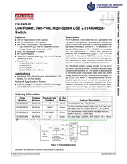
19. rence The FSUSB30 contains special circuitry on the D D pins which allows the device to withstand an overvoltage condition when powered off This device is also designed to minimize current consumption even when the control voltage applied to the S pin is lower than the supply volt age Vcc This feature is especially valuable to ultra portable applications such as cell phones allowing for direct interface with the general purpose I Os of the baseband processor Other applications include switch ing and connector sharing in portable cell phones PDAs digital cameras printers and notebook computers Ordering Information Order Package ProductCode Eco Number Number Top Mark Status Package Description FSUSB30L10X MAC010A FJ RoHS 10 Lead MicroPak 1 6 x 2 1mm 14 Terminal Depopulated Quad Very Thin Flat Pack Be d n A Green No Leads DQFN JEDEC MO 241 2 5 x 3 0mm 10 Lead Molded Small Outline Package MSOP FSUSB30MUX MUA10A FSUSB30 Green JEDEC MO 187 3 0mm Wide FSUSB30UMX MLP010A GJ Green 10 Lead Quad Ultrathin MLP UMLP 1 4 x 1 8mm USB2 0 Controller Set Top Box STB CPU or DSP Processor DVR or Mass Storage Controller 9 For Fairchild s definition of green Eco Status please visit http vvvvvv fairchildsemi com company green rohs green html USB Connector Figure 1 Typical Application MicroPak is a trademark of Fair
20. rly used in accordance with instructions for use provided in the labeling can be reasonably expected to result in a significant injury of the user PRODUCT STATUS DEFINITIONS PowerTrench Programmable Active Droop OFET QIT Quiet Series RapidConfigure O Saving our world ImVVAWKVY at a time SmartMax SMART START SPM STEALTHTM SuperFET SuperSOT 3 SuperSOT 6 SuperSOT 8 SupreMOSTM SyncFET SYSTEM GENERAL safety or effectiveness The following indudes registered and unregistered trademarks and service marks owned by Fairchild Semiconductor and or its global subsidiaries and is not The Power Franchise tha ane r TinyBoost TinyBuck TinyLagic TINYOPTO TinyPower TinyPVVMT TinyVVire pSerDes s UHC Ultra FRFET UniFET vcx VisualMaxt EZSWITCH and FlashWriter are trademarks of System General Corporation used under license by Fairchild Semiconductor FAIRCHILD SEMICONDUCTOR RESERVES THE RIGHT TO MAKE CHANGES WITHOUT FURTHER NOTICE TO ANY PRODUCTS HEREIN TO IMPROVE REUABILUITY FUNCTION OR DESIGN FAIRCHILD DOES NOT ASSUME ANY LIABILITY ARISING OUT OF THE APPLICATION OR USE OF ANY PRODUCT OR CIRCUIT DESCRIBED HEREIN NEITHER DOES IT CONVEY ANY L CENSE UNDER ITS PATENT RIGHTS NOR THE RIGHTS OF OTHERS THESE SPECIFICATIONS DO NOT EXPAND THE TERMS OF FAIRCHILD S WORLDWIDE TERMS AND CONDITIONS SPECIFICALLY THE WARRANTY THER
21. v 1 1 6 13 www fairchildsemi com YoIMS sdq yogr 0 2 ASN p ds uBH 3 4044 OAAL MOdg MO7 OEASNSSA Physical Dimensions 2x k o 101c 100 BI 2 10 L LL PIN 1 IDENT 1 TOP VIEW 0 35 10X 0 25 10X 7 LAND PATTERN RECOMENDATION ZES o 0 05 0 00 Cl R 0 10 t H L g aa x oa L qunun As BOTTOM VIEW NOTES A PACKAGE CONFORMS TO JEDEC M0255 VARIATION UABD B DIMENSIONS ARE IN MILLIMETERS C DIMENSIONS AND TOLERANCES CONFORMS TO ASME Y14 5M 1994 MAC010ARevC Figure 17 10 Lead MicroPak 1 6 x 2 1mm For tape and reel specifications visit Fairchild s website http Avww fairchildsemi com products logic pdf micropak_tr pdf Package drawings are provided as a service to customers considering Fairchild components Drawings may change in any manner without notice Please note the revision and or date on the drawing and contact a Fairchild Semiconductor representative to verify or obtain the most recent revision Package specifications do not expand the terms of Fairchild s worldwide terms and conditions specif ically the warranty therein which covers Fairchild products Always visit Fairchild Semiconductor s online packaging area for the most recent package drawings http www fairchildsemi com packaging YdIMS sdq yogr 0 2 ASN p ds uBH 410g OML aMOdg MO DEASNSSA 2
Download Pdf Manuals

Related Search
FAIRCHILD FSUSB30 handbook