SEMTECH ELECTRONICS MCR100-3 MCR100-8 handbook
Contents
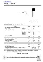
1. Latching Current uA 10 5 20 35 50 65 80 95 Ty Junction Temperature Figure 4 Typical Latching Curent Versus Junction Temperature 10 40 25 110 MAXIMUM TJ 25 MAXIMUM TJ 110 It Instantaneous On State Current AMPS o 0 5 0 8 1 1 17 20 23 26 29 32 35 Vr Instantaneous On State Voltage volts Figure 6 Typical On State Characteristics 1 4 DNY 180 900 REGIST DAV aia THE 4 ISO 9001 2000 Certificate No 556 1996 AQ RGC RvA Dated 06 12 20032. 0 D MCR100 3 D 0 MCR100 3 MCR100 8 a oG A K Tl 123 1 Cathode 2 Gate 3 Anode TO 92 Plastic Package Weight approx 0 18g MAXIMUM RATINGS T 25 C unless otherwise noted an Peak Repetitive Forward and Reverse Blocking Voltage Note 1 MCR100 3 T 7225 to 125 C Rex 1KQ MCR100 4 Vorm MCR100 5 d MCR100 6 VnnM MCR100 7 MCR100 8 Forward Current RMS All Conduction Angles Lade Peak Forward Surge Current T 25 C 1 2 Cycle Sine Wave 60Hz Circuit Fusing t 8 3ms Peak Gate Power Forward T 25 C Average Gate Power Forward T 25 C Peak Gate Current Forward T 25 C 300us 120PPS Peak Gate Voltage Reverse Operating Junction Temperature Range Rated Very and Vprm Storage Temperature Range Note 1 Ratings apply for zero or negative gate voltage however positive gate voltage shall not be applied 10 concurrent with negative potential on the anode GSP FORM A IS AVAILABLE 0 9001 1 REGI P ISO 9001 2000 Certificate No 5556 1996 AQ RGC RvA Dated 06 12 2003 MCR100 3 MCR100 8 CHARACTERISTICS Tc225 C Rex 1K unless otherwise noted Peak Forward or Reverse Blocking Current DRM IRRM Forward On Voltage Vom 1 7 Volts Gate Trigger Current Continuous dc Note 1 lor 200 LA Anode Voltage 7Vdc R 2100 Ohms ES ed Lil Gate Trigger Voltage Continuous dc Volts Anode Voltage 7Vdc R 2100 Ohms Anode Voltage Rated Vpgy R 2100 Ohms s Current Pm
3. e mewemeseeem O C t I Note 1 Rex current is not included in measurement GSP FORM AIS AVAILABLE SEMTECH ELECTRONICS LTD Wholly owned subsidiary of Honey Technology Ltd gr qo o9 30911 REGI ISO 9001 2000 Cerificate No 5556 1996 AG RGC RvA Dated 06 12 2003 MCR100 3 MCR100 8 Gate Trigger Current UA 10 5 20 35 50 65 80 Ty Junction Temperature Figure 1 Typical Gate Trigger Curent Versus Junction Temperature 40 25 95 1000 Holding Current pA 10 40 25 10 5 20 35 50 65 80 95 110 Ty Junction Temperature Figure 3 Typical Holding Curent Versus Junction Temperature e f DC e 180 N o o e a e Tc Maximum Allowable Case Temperature 7 90 0 4 60 0 0 1 0 3 Irreus RMS On State Current AMPS Figure 5 Typical RMS Current Derating 30 A o 0 2 0 5 110 1 0 0 9 0 8 0 7 0 6 0 5 0 4 0 3 Gate Trigger Voltage volts 0 2 40 25 10 5 20 35 50 65 80 95 110 Ty Junction Temperature Figure 2 Typical Gate Trigger Voltage Versus Junction Temperature 1000 e eo
Download Pdf Manuals

Related Search
SEMTECH ELECTRONICS MCR100 3 MCR100 8 handbook