DATALOGIC Powered Vehicle Dock User Manual
Contents
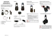
1. Figure 13 A Datalogic Memor Powered Vehicle Dock 94A151121 B Win Net Serial Cable HRS ST40x 18S CV 94A051022 C Portable Printer TECHNICAL FEATURES Datalogic Memor Powered Vehicle Dock Electrical Features Power Supply from 10 to 32 VDC mobie computer mobile computer Quiescent Consumption CLA Dock no load Quiescent Consumption CLA only no load Indicators Charge Time Li lon Battery max 4 hours Communication Features Interface RS232 Baud Rate RS232 up to 115200 b sec Environmental Features Working Temperature 0 to 50 C 32 to 140 F Storage Temperature 20 to 70 C 4 to 158 F Humidity 90 non condensing Sinusoidal Vibration 14 mm 2 to 10Hz 1 5mm 13 to Resistance 55 Hz EN 60068 2 6 2 gn 70 to 200 Hz 2 hours on each axis Frequency Range 5 1000 Hz acceleration RMS 3 1 g initial slope 26 dB octave 5 10 Hz final slope 3 dB octave 10 1000 Hz 1 hour on each axis Bump Resistance 25 G 6 ms 500 up amp 500 down EN 60068 2 29 bumps on each axis 30 G 11ms 3 shocks on each axis EN 60068 2 27 Dimensions dock 203 x 84 x 62 mm 8 12 x 3 36 x 2 48 Weight dock 140 g 5 6 oz Weight CLA Adapter 180 g 7 2 oz Random Vibration Resistance EN 60068 2 64 Battery must be charged at a temperature ranging from 0 to 40 C For the GSM models the maximum recommended temperature is 35 C At higher values the charging may slow down2. When the battery is exhausted the GSM turns off and it is not working until the battery is charged or changed kk Only valid for mounting with Ram Mount Adjustable Arm
3. Plug in the cigarette lighter adapter into the Battery Female Adapter Figure 10 3 Insert the Power Adapter Cable output connector in the dock Memor power port see the previous section To avoid battery waste it is recommended to connect the dock to a power connection point switched by the ignition key NOTE AN When connecting the Battery Female Adapter cable to the power connection point ensure that it does not CAUTION pass by sharp or very hot surfaces BATTERY CHARGING The dock provides battery charging for the Datalogic Memor when powered The Datalogic Memor will charge its installed battery when power is applied to the dock INSERTING THE DATALOGIC MEMOR IN THE DOCK To insert the Datalogic Memor into the dock perform the following steps 1 Slide the Memor into the dock 2 Push downwards to insert the Memor until it is firmly seated in the dock Figure 11 REMOVING THE DATALOGIC MEMOR FROM THE DOCK To remove the Datalogic Memor from the dock grasp the mobile computer and lift it straight uowards while pushing the top of the dock backwards Figure 12 CONNECTIONS RS232 Connection Datalogic Memor Powered Vehicle Dock can be connected to a device i e a printer or a powerscan by means of an RS232 interface Connect to the RS232 port of the dock to a Win Net Serial Cable Once the device has been turned on insert the Datalogic Memor into the dock
4. DATALOGIC Datalogic Memor Powered Vehicle Dock The Datalogic Memor Powered Vehicle Dock allows charging the Datalogic Memor mobile computer battery and holding it securely in your vehicle It also functions as a serial communication interface between a device typically a printer or a powerscan and the RS232 contacts on the mobile computer THE PACKAGE The dock package includes the following items m Figure 1 Ner Datalogic Memor Powered Vehicle Dock 94A151121 Power Adapter Cable Battery Female Adapter Fuse Holder Stylus Holder Dual Lock Label IMGOB gt S xr Sr 852000481 Rev A THE DOCK Figure 2 A Mounting Holes D Power Connector B LED Indicator E RS232 Connector C Dual Lock Label Adhesive Strip Seat THE POWER ADAPTER CABLE Figure 3a Figure 3b A Green LED B Fuse 2 5A 250V When the Power Adapter Cable is powered the green LED lights up The fuse can be easily replaced by unscrewing the ring nut and removing the cap see Figure 3b MOUNTING OPTIONS The dock can be mounted on the desired surface using either the Dual Lock Label or the Ram Mount MOUNTING WITH DUAL LOCK LABEL Figure 4 This procedure is suggested when mounting the dock on flat surfaces 1 Select a mounting location allowing an easy access to the dock connector panel 2 carefully clean the adhesive strip seat on the rear of the dock to remove any impurities tha
5. r a in the power port at the right bottom of the dock see figure 7a When the dock is powered the green LED lights up b in the port at the bottom of the mobile computer see figure 7b Figure 7a Figure 7b Make sure your vehicle s output voltage is between 10V to 32V and is capable of supporting a 2000MA current drain If you have any concerns regarding CAUTION this refer to your vehicle owner s manual When the Power Adapter Cable is connected to the Memor it is recommended not to lift the mobile computer by the Power Adapter Cable CAUTION Powering the dock Memor using the Battery Female Adapter For connection to the vehicle power source through the Battery Female Adapter it is necessary to prepare the power cable termination to connect the dock to the vehicle power source Red wire connect to a V 10 to 32 Vdc vehicle power source Black wire connect to the vehicle ground wire or chassis ground In this case it is mandatory to use the slow blow 8A 250V with holder supplied with the dock 1 Verify that the fuse is contained within the holder then splice it to the end of the red wire of the cable Make the distance between fuse holder and power connection point as short as possible and apply a caution label on the fuse holder Once the power cable termination has been completed it is possible to connect the dock to the vehicle power Figure 8 Red Wire Figure 9 2
6. t could reduce adhesion 3 remove the protection film from the adhesive side of one of the available labels and stick it on the dock surface 4 remove the protection film from the adhesive side of the remaining label and stick it on the vehicle surface smooth and clean for better adhesion 5 affix the dock to the vehicle surface The Dual Lock label must be stuck at least 48 hours before the dock is submitted to mechanical stress CAUTION MOUNTING WITH RAM MOUNT ADJUSTABLE ARM The Ram Mount Adjustable Arm allows wide range of rotation for the dock It can be mounted on any flat surface while the ball joints enable position flexibility 1 Align the adjustable arm with the four screw holes on the rear of the dock as shown in Figure 5 Figure 5 2 Secure the adjustable arm to the rear of the dock using the four M 4 X 25 UNI 7687 ZB screws as shown in Figure 6 Figure 6 Install only on properly grounded mobile platforms If this dock is used on an electric vehicle ensure that no part of the dock and mobile computer can come CAUTION into contact with the vehicle chassis Electrical discharges can develop on these vehicles which can damage the dock and or mobile computer POWERING THE DOCK Powering the dock Memor in your vehicle 1 Plug in the supplied cigarette lighter adapter into your vehicle s cigarette lighter or 12V or 24V power source 2 insert the Power Adapter Cable output connecto
Download Pdf Manuals

Related Search
DATALOGIC Powered Vehicle Dock User Manual loading dock design manual alogic docking station drivers industrial scientific docking station manual alogic dock station driver alogic driver docking station