IXYS IXGH 20N60BD1 IXGT 20N60BD1 handbook
Contents
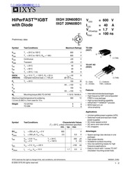
1. HiPerFAST IGBT with Diode IXGH 20N60BD1 IXGT 20N60BD1 C Preliminary data S E Symbol Test Conditions Maximum Ratings Voes T 25 C to 150 C 600 V Voor T 25 C to 150 C Ro 1 MQ 600 V V GES Continuous 20 V V oen Transient 30 V c25 Toe 25 C 40 A l T 90 C 20 A la T 25 C 1 ms 80 A SSOA Vo 15 V T 125 C R 22 lon 40 A RBSOA Clamped inductive load L 100 uH 0 8 Voes P T 25 C 150 W T 55 150 C Tiy 150 C ie 55 150 C M Mounting torque M3 TO 247AD 1 13 10 Nm b in Maximum lead temperature for soldering 300 C 1 6 mm 0 062 in from case for 10 s Weight TO 247AD 6 g TO 268 4 g Symbol Test Conditions Characteristic Values T 25 C unless otherwise specified min typ max BV s 250yA V 0V 600 V Vem lL 250 uA Vo Vo 2 5 55 V Voe 0 8 Vots T 25 C 200 pA Vee OV T 150 C 3 mA lees Voge OV Vo 20 V a 100 nA Ves ls beggs Vee 15 V 1 7 2 0 IXYS reserves the right to change limits test conditions and dimensions 2000 IXYS All rights reserved Vic 600 V Ise 40 A CE sat typ 1 7 V OR 100 ns TO 268 IXGT TO 247 AD IXGH G G Gate C Collector E Emitter TAB Collector Features e International standard packages e High frequency IGBT and antiparallel FRED in one package High current handling capability HiPerFAST HDMOS process e MOS Gate turn on drive simplicity Applications e Uninterru2. Values T 25 C unless otherwise specified F i lt Symbol Test Conditions min typ max T te V l 30A Va 0 V T 150 C 16 V Pulse test t lt 300 us duty cycle d lt 2 T 25 C 2 5 V mie L3 gn l 30A V 0 V di_ dt 100 A us 6 A L t V gt 100 V T 100 C 100 ns l 1 A di dt 100 A us Va 30 V T 25 C 25 ns Dim Millimeter Inches Min Max Min Max Rije A 4 9 51 2 7 2 9 02 25 1 15 1 45 1 9 2 1 4 65 13 80 14 00 15 85 16 05 13 3 13 6 5 45 BSC 215 BSC 18 70 19 10 736 752 2 40 2 70 094 106 1 20 1 40 047 055 1 00 1 15 039 045 0 25 BSC 010 BSC 3 80 4 10 150 161 in Recommended Footprint K 0 653 16 59 5 ee N Ei D E S Ei 0 118 3 00 m 0 215 5 46 Ff fF r o m m O O f IXYS MOSFETS and IGBTs are covered by one or more of the following U S patents 2000 IXYS All rights reserved 4 835 592 4 881 106 5 017 508 5 049 961 5 187 117 5 486 715 2 2 4 850 072 4 931 844 5 034 796 5 063 307 5 237 481 5 381 025
3. ptible power supplies UPS e Switched mode and resonant mode power supplies e AC motor speed control e DC servo and robot drives e DC choppers Advantages e Space savings two devices in one package e High power density Suitable for surface mounting e Very low switching losses for high frequency applications e Easy to mount with 1 screw TO 247 insulated mounting screw hole 98566A 3 99 1 2 IXYS XGT 20N60BD1 Symbol Test Conditions Characteristic Values T 25 C unless otherwise specified min typ max TO 247 AD IXGH Outline for V Clamp gt 0 8 Voes higher T or CES increased R 1 0 mg Jis l z ls Vog 10V 9 17 S Pulse test t lt 300 us duty cycle lt 2 Cies 1500 pF C Va 25V V 0 V f 1 MHz 150 pF Ces 40 pF Q 55 nC Q l leey Va 15 V Voe 0 5 Voes 12 nC Qo 20 nC Millimeter lii Inductive load T 25 C 15 ns Min Max A 19 81 20 32 0 780 t b ley Vee 15 V L 100 uH 25 ns oe Lich Voge 0 8 Voes Rg Ry 10 Q 110 200 ns C 5 75 16 26 0 610 t Remarks Switching times may increase 100 150 ns D 3 55 3 65 0 140 0 7 15 taron Inductive load T 125 C ti E on Voz 0 8 V ko ky Vee 15V L 100 pH er i 0 75 mJ cs Rg Ry 10 Q tror Remarks Switching times may increase 220 ee t for V Clamp gt 0 8 Voes higher T or 140 ns E increased Ro 12 mJ off 5 Rac 0 83 K W Rinck TO 247 0 25 K W Reverse Diode FRED Characteristic
Download Pdf Manuals

Related Search
IXYS IXGH 20N60BD1 IXGT 20N60BD1 handbook