ANALOG DEVICES 23 ns 65 ns Low Voltage Comparators CMP401/CMP402 handbook
Contents
1. 9jc Units 16 Lead SO S 113 37 C W 16 Lead TSSOP RU 180 37 C W NOTES Absolute Maximum Ratings apply to packaged parts unless otherwise noted The analog input voltage is equal to 7 V or the analog supply voltage whichever ORDERING GUIDE Temperature Package Package Model Range Description Option CMP401GS 40 C to 125 C 16 Lead SOIC R 16A CMP401GRU 40 C to 125 C 16 Lead TSSOP RU 16 CMP402GS 40 C to 125 C 16 Lead SOIC R 16A CMP402GRU 40 C to 125 C 16 Lead TSSOP RU 16 V DIG is less Q a is specified for the worst case conditions i e Dua is specified for device soldered Kata in circuit board for SOIC and TSSOP packages Figure 1 Simplified Schematic 1 j MWN PIN CONFIGURATIONS 16 Lead Narrow SO 16 Lead S Suffix TSSOP RU Suffix outs i e 16 our c 16 oral Blow ME V DIG 3 ida 114 DIG GND AAA cMP401 E Bis AND v ANA 4 402 t3 v ANA ANA C E n IN D ANA C E IN D N A 5 Nettosat ND IN g Ey tesi Inc N B Y L N C IN A 6 IND 8 9 INB INC IN B 8 INC CAUTION ESD electrostatic discharge sensitive device Electrostatic charges as high as 4000 V readily accumulate on the human body and test equipment and can discharge without detection Although the CMP401 CMP402 features proprietary ESD protection circuitry permanent damage may occur on devices subjected to high energy electrostatic disch2. SOIC R 16A 16 9 NS 0 1574 4 00 e 0 1497 3 80 1 8 0 2440 6 20 0 2284 5 80 Y a gt f coos d T mo de gt lt gt e 0 0098 0 25 0 0500 1 27 0 0192 0 49 0 0099 0 25 0 0500 1 27 0 0040 0 10 BSC 0 0138 0 35 0 0075 0 19 0 0160 0 41 16 Lead TSSOP RU 16 33 J j VWN 0 006 0 15 0 002 0 05 0 0433 y HER d gt F lt MAX 0 028 0 70 0 0256 0 0119 ps 30 0 020 0 50 PLANE O29 0 0075 0 9 DIEN Revision History Location Page Data Sheet changed from REV 0 to REV A Edits to GENERAL DESCRIPTION 2220222425 A a ds RAM EY AERE Gn 1 Edits to ABSOLUTE MAXIMUM RATINGS ici a bx sane ae a cai d A de 4 Fits to PACKAGE TYPE a A A E 4 Edits to ORDERING GUIDE 00 bl da A 4 Deleted DICE CHARACTERISTICS sui EA A a Ekle es Ee ely ad and act 4 Edits to CMP401 CMP402 PIN CONFIGURATIONS 00 0 4 8 REV A C00267 0 2 02 A PRINTED IN U S A
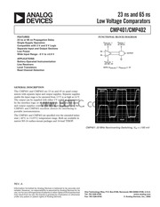
3. 5V IN OUTPUT IN VANALOG 0V OR 5V NOTE VANALOG Dana oe lz 3V CMP401 20 MHz Noninverting Switching Viy 100 mV One Technology Way P O Box 9106 Norwood MA 02062 9106 U S A Tel 781 329 4700 www analog com Fax 781 326 8703 Analog Devices Inc 2002 CMP401 CMP402 SPECIFICATIONS ELECTRICAL SPECIFICATIONS O Vana V pig 5 0 V Von 0 1 V 40 C lt T lt 125 C unless otherwise noted Parameter Symbol Conditions Min Typ Max Unit INPUT CHARACTERISTICS Offset Voltage Vos Ta 25 C 3 mV Vos 4 mV Hysteresis 2 mV Input Bias Current L Ta 25 C 3 uA Ip 4 uA Input Offset Current los 3 uA Input Common Mode Voltage Range Vom 0 4 0 V Common Mode Rejection CMRR 0 1 V lt Vey lt 3 9 V 60 dB Large Signal Voltage Gain Avo Rr 10 kQ 10 V mV Offset Voltage Drift AVos AT 1 uV C OUTPUT CHARACTERISTICS Output High Voltage Non Ion 3 2 mA 4 6 V Output Low Voltage VoL lor 3 2 mA 0 2 V POWER SUPPLY Power Supply Rejection Ratio PSRR V ANA and V prc 2 7 V to 6 V 60 dB Analog Supply Current CMP401 Tana Ta 25 C 6 5 mA Digital Supply Current CMP401 Ipic Vo 0 V Rr Ta 25 C 2 0 mA Analog Supply Current CMP401 Tana 8 0 mA Digital Supply Current CMP401 Ipic Vo 0 V Rr e 2 25 mA Analog Supply Current CMP402 Tana Ta 25 C 1 4 mA Digital Supply Current CMP402 Ipic Vo 0 V Rr Ta 25 C 2 0 mA Analog Supply Current C
4. ANALOG DEVICES 23 ns and 65 ns Low Voltage Comparators CMP401 CMP402 FEATURES 23 ns or 65 ns Propagation Delay Single Supply Operation Compatible with 3 V and 5 V Logic Separate Input and Output Sections Low Power Wide Input Range 5 V to 3 9 V APPLICATIONS Battery Operated Instrumentation Line Receivers Level Translators Read Channel Detection GENERAL DESCRIPTION The CMP401 and CMP402 are 23 ns and 65 ns quad comp arators with separate input and output supplies Separate supplies enable the input stage to be operated from 3 V to as high as 6 V The output can be supplied with either 3 V om5 V as determined by the interface logic or ayailabl suippli s Independent input and output supplies combiged witHifasg propagation nake the CMP401 and CMP402 excellent choices for interfacing to portable instrumentation The CMP401 and CMP402 are specified over the extended indus trial 40 C to 125 C temperature range Both are available in narrow SO 16 surface mount packages and 16 lead TSSOP REV A Information furnished by Analog Devices is believed to be accurate and reliable However no responsibility is assumed by Analog Devices for its use norforany infringements of patents or other rights ofthird parties that may result from its use No license is granted by implication or otherwise under any patent or patent rights of Analog Devices FUNCTIONAL BLOCK DIAGRAM VANALOG VDIGITAL 0V OR 5V 3V OR
5. MP402 Tana 1 75 mA Digital Supply Current CMP402 Ipic Vo 0 V Rr 2 25 mA DYNAMIC PERFORMANCE Propagation Delay CMP401 tp 10 Y St ith 20 mV OD BOC Cor AL gt LAU mV St ith 5 Ta 25 C 33 ns tp 100 mV Step with 20 mV OD 30 ns Propagation Delay CMP402 tp 100 mV Step with 20 mV OD Ta 25 C 54 65 ns tp 100 mV Step with 5 mV OD Ta 25 C 60 ns tp 100 mV Step with 20 mV OD 75 ns ELECTRICAL SPECIFICATIONS Van Vow 3 0 V Ven 0 1 V T 25 C unless otherwise noted Parameter Symbol Conditions Min Typ Max Unit INPUT CHARACTERISTICS Offset Voltage Vos 4 5 mV Input Common Mode Voltage Range Vom 0 2 0 V Input Differential Voltage Range VpirE 2 0 V Common Mode Rejection CMRR 0 1 V lt Vem lt 1 9 V 60 dB OUTPUT CHARACTERISTICS Output High Voltage Vou log 3 2 mA 2 6 V Output Low Voltage VoL lor 3 2 mA 0 25 V POWER SUPPLY Power Supply Rejection Ratio PSRR V ana and V piG 2 7 V to 6 V 60 dB Analog Supply Current CMP401 Tana mA Digital Supply Current CMP401 Ipic Vo 0V RL e mA Analog Supply Current CMP402 Tana 1 2 mA Digital Supply Current CMP402 Ipic Vo 0V RL oo mA DYNAMIC PERFORMANCE Propagation Delay CMP401 tp 100 mV Step with 20 mV OD 32 ns Propagation Delay CMP402 tp 100 mV Step with 20 mV OD 70 ns 9 REV A CMP401 CMP402 ELECTRICAL SPEC IFICATIONS O Vana 5 V Vp 5 0 V Ta 25 C unless otherwise noted Parameter Symbol Conditions Min Typ Max Unit I
6. NPUT CHARACTERISTICS Offset Voltage Vos Vom 0V 3 mV Input Common Mode Voltage Range Vom 5 0 4 0 V Input Differential Voltage Range VpirE 8 0 V Common Mode Rejection CMRR 4 9 V lt Vem lt 3 9 V 60 dB Offset Voltage Drift AVos AT 1 5 uV C POWER SUPPLY Power Supply Rejection Ratio PSRR Vana t2 V to 6 V 60 dB Analog Supply Current CMP401 lana 6 5 mA Digital Supply Current CMP401 Ipic Vo 0V RL o 2 0 mA Analog Supply Current CMP402 Tana 2 0 mA Digital Supply Current CMP402 Ipic Vo 0 V Rr 2 0 mA DYNAMIC PERFORMANCE Propagation Delay CMP401 tp 100 mV Step with 20 mV OD 23 ns Propagation Delay CMP402 tp 100 mV Step with 20 mV OD 65 ns NOTES 1Offset voltage is defined as Voss Vos 2 Specifications subject to change without notice ww BDI C conh ALI REV A CMP401 CMP402 ABSOLUTE MAXIMUM RATINGS Total Analog Supply Voltage 16V Digital Supply Voltage 7V Analog Positive Supply Digital Positive Supply 200 mV Input Voltage sin sao adean Daaa cece eee KA Differential Input Voltage 9 V Output Short Circuit Duration to GND Indefinite Storage Temperature Range S RU Package Operating Temperature Range CMP401G CMP402G Junction Temperature Range S RU Package 65 C to 150 C 40 C to 125 C 65 C to 150 C Lead Temperature Range Soldering 60 sec 300 C Package Type Oja
7. ROPAGATION DELAY ns VAN Vpic 5V Van 0V TO 5V Rs 500 TA 25 C 0 0 100 200 300 400 CAPACITIVE LOAD pF 500 TPC 11 CMP401 Propagation Delay vs Capacitive Load VAN VpiG Ta 25 C VaN OV TO 5V Rg lt 500 C 15pF PROPAGATION DELAY ns RI 3 4 5 P SUPPLY VOLTAGE d TPC 14 CMP401 Propagation Delay vs Supply Voltage 2 0 1 6 5V 1 2 0 8 DIGITAL DC SUPPLY CURRENT mA 0 0 75 50 25 0 TPC 17 CMP401 Digital Supply TEMPERATURE C Current vs Temperature e LLLLLL s A 25 50 75 100 125 150 PROPAGATION DELAY ns CAPACITIVE LOAD pF TPC 12 CMP402 Propagation Delay vs Capacitive Load 1000 Ta 25 C gt 100 o ARAIL o 5 10 E ARAIL 2 o ef W a 100 1000 10000 rid AL LOAD CURRENT pA 100000 TPC 15 CMP401 CMP402 Delta Out put Swing from Power Supplies vs Load Curren 2 0 t 1 6 5V 1 2 0 8 0 4 3 DIGITAL DC SUPPLY CURRENT mA 0 0 75 50 25 0 25 50 75 100 TEMPERATURE C 125 150 TPC 18 CMP402 Digital Supply Current vs Temperature REV A Typical Performance Characteristics CMP401 CMP402 DIGITAL SUPPLY CURREN
8. T mA DIGITAL SUPPLY VOLTAGE V TPC 19 CMP401 Digital Supply Current vs Digital Supply Voltage o EI ANALOG SUPPLY CURRENT mA o o 0 4 I 75 50 25 0 25 50 Sei IM Pepa TEMPERATURE M Ww TPC 22 CMP402 Analog Supply Current vs Temperature REV A ANALOG SUPPLY CURRENT mA 1 6 tf 40 C I E ui 25 C tc tc 8 125 C gt 0 8 di n n 2 o EET d 04 E S a 0 0 1 2 3 4 5 DIGITAL SUPPLY VOLTAGE V TPC 20 CMP402 Digital Supply Current vs Digital Supply Voltage 7 0 6 0 125 C 5 0 25 C 40 C 4 0 Mr SA aa 4l5 6 f e b TPC 23 CMP401 Analog Supply Current vs Analog Supply Voltage ANALOG SUPPLY CURRENT mA 7 ANALOG Suppuy VoErAGE V D i ANALOG SUPPLY CURRENT mA 7 0 6 0 5 0 4 0 3 0 5V 5V 3V 2 0 75 50 25 0 25 50 75 5d 125 150 TEMPERATURE TPC 21 CMP401 Analog Supply Current vs Temperature 14 TPC 24 CMP402 Analog Supply Current vs Analog Supply Voltage CMP401 CMP402 OUTLINE DIMENSIONS Dimensions shown in inches and mm 16 Lead Narrow
9. TURE C TPC 4 CMP402 Propagation Delay TPC 5 CMP401 Propagation Delay TPC 6 CMP402 Propagation Delay vs Temperature 5 mV OD vs Temperature 20 mV OD vs Temperature 20 mV OD Van Vpio V VAN VpiG 5V Van 0VTO 5V Van 0VTO 5V TA 25 C 2 TA 25 C 2 I 1 1 lt gt gt E d i 2 a a S lt lt lt g 6 lt lt n D n a D n 0 0 10 100 1k 10k 100k 10 100 1k 10k 100k 0 2 3 4 5 6 SOURCE RESISTANCE Q SOURCE RESISTANCE Q POSITIVE SUPPLY VOLTAGE V TPC 7 CMP401 Propagation Delay TPC 8 CMP402 Propagation Delay TPC 9 CMP401 Propagation Delay vs vs Source Resistance 20 mV OD vs Source Resistance 20 mV OD Supply Voltage 20 mV OD REV A b CMP401 CMP402 VAN VpIG VaN OV TO 5V Rs lt 509 C 15pF TA 25 C PROPAGATION DELAY ns 1 2 3 4 5 6 POSITIVE SUPPLY VOLTAGE V TPC 10 CMP402 Propagation Delay vs Supply Voltage 20 mV OD 1200 Van VpiG Van 0V TO 5V Rs 500 C 15pF Ta 25 C 1000 SLEWRATE V us gt e N e e 1 2 3 4 V A POSITIVE SUPPLY VOLTAGE VV TPC 13 CMP401 CMP402 Slew Rate vs Positive Supply Voltage 2 5 2 0 15 0 5 INPUT OFFSET VOLTAGE mV 0 75 50 25 0 25 50 75 100 125 150 TEMPERATURE C TPC 16 CMP401 CMP402 Input Offset Voltage vs Temperature PpELAY P
10. arges Therefore proper ESD precautions are recommended to avoid performance degradation or loss of functionality 4 WARNING DIG GND eer ESD SENSITIVE DEVICE REV A Typical Performance Characteristics CMP401 CMP402 Van Vpig 5V VAN Vpig 5V Van OVTO 5V Van 0VTO 5V a Rs lt 500 C 15pF Rs 500 C 15pF S T o Ta 25 C 2 gt Ta 25 C 1 lt lt gt 3 3 3 a PpELAY a m o z E 8 lt lt lt lt g 6 a a lt 5 E a o 0 10 20 30 40 50 0 10 20 30 40 50 50 25 0 25 50 75 100 125 OVERDRIVE mV OVERDRIVE mV TEMPERATURE C TPC 1 CMP401 Propagation Delay TPC 2 CMP402 Propagation Delay TPC 3 CMP401 Propagation Delay vs Overdrive vs Overdrive vs Temperature 5 mV OD 90 30 60 VAN Vpig 5V ao Van 0V TO 5V ds 5 2 Rg lt 500 C 15pF 2 2 I I I gt 70 3 20 3 40 md PpELAY u o a a a z z 15 z 30 S E E E lt lt lt g 10 g 20 3 5 VAN VpiG DN x T E 10 Van 0VTO 5V Rs lt 500 CL 15pF 0 25 50 f 50 25 ol 25 sof 75 100 12 0 25 50 75 10 125 TEMPERATURE LA l1 TEMPERATURE Vis A TEMPERA
Download Pdf Manuals

Related Search
ANALOG DEVICES 23 ns 65 ns Low Voltage Comparators CMP401/CMP402 handbook