IC+ IP178C/IP178C LF/IP178CH/IP178CH LF Datasheet
Contents
1. MDC AA AA AA AJAJAJ AA AAA AA A AAA AL AL HM A A A A A AI A A A A EC E MDIO A 1 1 0110 1 00 001 000001 00011 0011 000 0 000141 1 de stat P AAAAARRRRR TAbbbbbbbbbbbbbbbb 4321043210 1111119876543210 write PHY e Reg Kate 543210 Register data MDC AT AT AT A A A AJA HA A AAA AA AAA AJA LA A A AAA AA A A A A z MDIO 1 1 0 11110 0 0 0 0 1 0 0 0 0 0 Z 00 011 0 0 0 1 0 0 0 010 0 0 0 1 1 de stat P AAAAARRRRR TA bbbbbbbbbbbbbbbb ide a 43921043210 1111119876543210 PHY SE z Reg ss 543210 Register data 47193 June 21 2007 Copyright O 2004 IC Plus Corp IP178Cx DS R12 IC IP178C IP178C LF IP178CH IP178CH LF Datasheet 2 13 SCA IP178C IP178CH performs SCA on each port and shows the test result on LED pins whenever pin SCA is pulled high The LED display is independent of LED SEL pins The following table shows the LED behavior of a port performing SCA LinK LED SPEED LE FDX LED SCA initiation Scan port by port Scan port by port Scan port by port iaaii Running Horse LED On 286ms gt Off 2s gt On 286ms gt Off 2s ee An open cable with length shorter than 50m open An open cable with length between 50m and 100m An open cable with length between 100m and 150m An shorted cable with Flash shorter than 50m An shorted cable with between 50m and 100m An shorted cable with Flash between 100m and 150m 2 14 Bandwidth control IP178C IP178CH p2. Symbol Description Trxcik Receive clock period 100 Mbps MII TsRxcik RXDV RXD to RXCLK setup time Thrxcik RXDV RXD to RXCLK hold time TRxCIk RXCLK ThRxCIk RXDV RXD 3 0 TsRxCIk b Transmit Timing Symbol Description Tesch Transmit clock period 100 Mbps MII Tarxcik TXCLK rising edge to TXEN TXD Trxcik nek TT TT D 1r TXEN TXD 3 0 Z 88 93 June 21 2007 Copyright O 2004 IC Plus Corp IP178Cx DS R12 Datasheet IP178C IP178C LF IP178CH IP178CH LF RMII Timing 3 3 3 a Receive Timing Requirements Description Clock period kep E 5 o RXDV RXD to RMIL CLK IN hold time RXDV RXD to RMII CLK IN setu Tsgxcik Tcik S NN NN IN RM11 CLK RXDV RXD 1 0 b Transmit Timing Description Clock period g edge to TXEN TXD RM11 CLK IN risin Tcik Tarxcik RMII CLK IN TXEN TXD 1 0 June 21 2007 IP178Cx DS R12 89 93 Copyright O 2004 IC Plus Corp IC IP178C IP178C LF IP178CH IP178CH LF Datasheet 3 3 4 SMI Timing a MDCIMDIO Timing Description MDC High Time MDC Low Time MDC period MDIO output delay MDIO setup time MDIO hold time MDC Tms T mh wo KK Write Cycle MDC BE Tcl
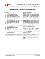
3. IP178C IP178CH applications continued An 8 port router application IF pin 53 EXTMII EN is pulled high then MII RMII interface is enabled IP178C IP178CH is connected to a CPU through MII RMII interface IP178C IP178CH works as an 8 port router MII RMII interface is set to be PHY mode and 100 Mbps full duplex in this application Router IP178C switch engine Mac MII RMII 1178CH MAC MAGO MAC7 PHY mode CPU PHY PHY PHY PHY 0 d ng 6 7 LAN port ople WAN ort j port ml ADSL WAN to ISP or D A Cable modem p Ethernet Ethernet zd LI 14 93 June 21 2007 Copyright 2004 IC Plus Corp IP178Cx DS R12 IC IP178C IP178C LF IP178CH IP178CH LF Datasheet 1 Pin description mas o owupn EE EE TOT RR MY EE REG OUT Regulator output voltage The internal regulator uses pin83 pin92 VCC O as reference voltage to control external transistor to generate a voltage source between 1 80v 2 05v If pin 53 EXTMII EN is pulled high then pin83 pin92 VCC O should be connected to 3 3v to generate 1 80v 2 05v voltage source If pin 53 EXTMII EN is pulled low then pin83 pin92 VCC O should be connected to 2 5v to generate 1 80v 2 05v voltage source BGRES Band gap resister It is connected to GND through a 6 19k 1 resistor in application circuit RXIPO 7 TP receive RXIMO 7 TXOPO 7 TP
4. RMII mode EXTMII EN 1 RMII MII 1 Mil MAC 1 MII MAC should be pulled high in spite of IP178C connecting to a MAC or a PHY AT gt 1 IP178C RXDV RXDV RXD 1 0 RXD 1 0 EXTMII EN RMII CLK IN e MAC HS RM11 CLK OUT gt REF CLK TXEN a TXEN TXD 1 0 a TXD 1 0 RM11 Mil IP178C RXDV TXEN RXD 1 0 TXD 1 0 EXTMII EN RMII CLK IN 4j PHY MII MAC RM11 CLK OUT gt REF CLK TXEN RXDV TXD 1 0 4 RXD 1 0 RM11 Mil Copyright amp 2004 IC Plus Corp 30 93 June 21 2007 IP178Cx DS R12 IC IP178C IP178C LF IP178CH IP178CH LF Datasheet LED display normal operation Normal operation LED O SEL LinK LED SPEED LED FDX LED Off link fail Off link fail Off half duplex On 10 Mbps link ok On 100 Mbps link ok On full duplex Flash Tx Rx Flash Tx Rx Off link fail Off 10 Mbps Off half duplex On link ok On 100 Mbps On full duplex Flash Rx Flash collision 10 Off link fail Off link fail Off half duplex On 10 Mbps link ok On 100 Mbps link ok On full duplex Flash Tx Rx Flash Tx Rx Flash collision Off link fail Off 10 Mbps Off half duplex On link ok On 100 Mbps On full duplex Flash Tx Rx Flash collision Flash behavior On 44ms Off 176ms D On 44ms 2 Wh
5. 31 11 15 0 87 7 0 PHY EEPROM SETTING 1 15 0 16 h0000 86 7 0 12 15 0 89 7 0 Pi PHY EEPROM SETTING 2 15 0 16 h0000 88 7 0 80 93 June 21 2007 Copyright O 2004 IC Plus Corp IP178Cx DS R12 IC IP178C IP178C LF IP178CH IP178CH LF Datasheet PAY wi ROM RW Bescipio berau Spanning tree control registers LL tree Spanning tree control registers LL registers 31 13 15 8 Forward en 13 15 1 port forwarding enabled 0 port forwarding disabled 13 14 1 port6 forwarding enabled 0 port6 forwarding disabled 13 13 1 port5 forwarding enabled 0 port5 forwarding disabled 13 12 1 port4 forwarding enabled 0 port4 forwarding disabled 13 11 1 port3 forwarding enabled 0 port3 forwarding disabled 13 10 1 port2 forwarding enabled 0 port2 forwarding disabled 13 9 1 port1 forwarding enabled 0 port1 forwarding disabled 13 8 1 portO forwarding enabled 0 portO forwarding disabled 13 7 0 Learning en 13 7 1 port7 learning enabled 0 port7 learning disabled 13 6 1 port6 learning enabled 0 port6 learning disabled 13 5 1 port5 learning enabled 0 port5 learning disabled 13 4 1 port4 learning enabled 0 port4 learning disabled 13 3 1 port3 learning enabled 0 port3 learning disabled 13 2 1 port2 learning enabled 0 port2 learning disabled 13 1 1 port1 learning enabled 0 port1 learning disabled 13 0 1 portO learning enabled 0 portO learni
6. C Router EXTMII EN 1 BI COLOR 0 VCC O D Router EXTMII EN 1 BI COLOR 1 VCC O REGOUT RESETB AVCC DVCC LED LED Note R is a pull up resistor for configuration It should be connected to VCC O NA REGOUT RESETB AVCC DVCC Note R is a pull up resistor for configuration It should be connected to VCC O 9 93 June 21 2007 Copyright O 2004 IC Plus Corp IP178Cx DS R12 IC LE IP178C IP178C LF IP178CH IP178CH LF Datasheet Pin diagram IP178C SCL MIL MAC 104 103 MDC RXGND1 RXVCC1 RXIP1 RXIM1 124 TXGND1 GND 128 127 126 125 123 TXOP1 122 TXOM1 ET Txveco1 120 TXOMO 119 TXOPO TEI TXGNDO 1177 RXGNDO HJ RXIMO EI RXIPO 114 RXvcco T13 TZ GND TT GND TT GND 1057 vee 108 vee 107 vec roe vee 705 SDA RXVCC2 102 MDIO RXIP2 101 TXCLK LONG PKT DIS RXIM2 100 P6 7 HIGH LINK LEDO RXGND2 99 COS EN LINK LED TXGND2 98 VCC SRAM TXOP2 5 97 LINK LED2 TXOM2 96 LINK LED3 Txvcc23 8 95 BI COLOR Txom3 CS 94 GND SRAM Txop3 30 93 MODBCK LINK LED4 TXGND3 92 vcc o RXGND3 91 BF STM EN LINK LED5 RXIM3 90 MDI MDIX EN LINK LED6 RXIP3 89 MLT3 DET LINK LED RXVCC3 88 GND O BGVCC 16 87 TXD0 LDPS DIS FDX_LEDO BGRES 86 TXD1 FDX LED BGGND 18 IP178C 85 TXD2 FDX LED2 P
7. PAY Mm Row mw Deseipion ra Port 1 MII register 0 5 ios Pesser Mi regbters 00 05 H PAY wi ROM Rw Description berau Port2 MI register ns Port 2 MII register 0 5 2 os Please refertowivegsiers00 05 PAY wi Row mw Deseipion Geo Port 3 MII register 0 5 3 os Please refertowilregsiers00 05 PAY Mm Row mw Description bea Port 4 MII register 0 5 Ca os Piease alerto Mi regbters 00 05 H PAY wi ROM RW Bescipion eut ean sma ns Port 5 MII register 0 5 Ps os es PHY Mi ROM Rw Description Default Port 6 Mil register 0 5 Port 6 MII register 0 5 Ps os es PAY Mm Row mw Deseipion ra Port 7 MII register 0 5 7 s Please refertowilregsiers00 05 56 93 June 21 2007 Copyright O 2004 IC Plus Corp IP178Cx DS R12 IC IP178C IP178C LF IP178CH IP178CH LF Datasheet PHY w ROM RAW Description Default EEPROM enable register Software reset register EEPROM enable register This register should be filled with 55AA in EERPOM register 0 and 1 IP178C IP178CH will examine the specified pattern to confirm if there is a valid EEPROM The initial setting is updated with the content of EEPROM only if the specified pattern 55AA is found Software reset register MII register O is software reset register User can reset IP178C IP17
8. 1 Link partner support 100BASE TX 0 Link partner does not support 100BASE TX 10BASE T full duplex 1 Link partner support 10BASE T full duplex 0 Link partner does not support 10BASE T full duplex 10BASE T 1 Link partner support 10BASE T 0 Link partner does not support 10BASE T 5 4 0 Selector Field 00000 Protocol selector of the link partner 54 93 June 21 2007 Copyright 2004 IC Plus Corp IP178Cx DS R12 IC IP178C IP178C LF IP178CH IP178CH LF Datasheet aaa Pepe onn During SCA mode the SCA result for each port will be stored at MII reg 05 Auto Negotiation Link Partner Base Page Ability SCA setting register 5 15 14 SCA line state These two bits indicate the cable status measured by SCA operation 3 test fail not complete 2 line okay 1 line open O line short 5 13 8 SCA_peak_val These bits indicate the absolute value and the maximum value of peak amplitude measured by SCA operation SCA peak pos 7 2 These bits indicate the position of peak amplitude measured by SCA operation When cable status is open or short the failure position is approximated as SCA peak pos 7 2 4 meters Ex SCA peak pos 7 2 6 b011001 the failure position is 25 4 100 meters SCA txsel These two bits indicate the TX phase of SCA operation 55 93 June 21 2007 Copyright O 2004 IC Plus Corp IP178Cx DS R12 IC IP178C IP178C LF IP178CH IP178CH LF Datasheet Basic MII registers of port 1 7
9. IP178Cx DS R12 76 AGING Aging enable 1 enable 300s aging timer default 0 disable aging function The function is valid only if pin 53 EXTMII EN is pulled low IC IP178C IP178C LF IP178CH IP178CH LF Datasheet Pin description continued Pinna Label mpe Descrip Advance operation parameter setting of switch engine P6 7 HIGH IPL1 Port6 port are set to be high priority port IO Packets received from port6 or port7 are handled as high priority packets if the function is enabled 1 enable O disabled default Itis an input signal during reset and its value is latched at the end of reset It acts as a link LED of port 0 after reset COS EN IPL1 Class of service enable IO Packets with high priority tag are handled as high priority packets if the function is enabled 1 enable 0 disabled default It is an input signal during reset and its value is latched at the end of reset It acts as a link LED of port 1 after reset VLAN ON IPL1 Turn on VLAN JO Enable a specific configuration of port base VLAN 0 disabled default 1 enable IP178C IP178CH are separated into 7 VLANS if this function is enabled and MII port is disabled The VLAN group is as follows PinS3EXTMILEN O Pin 53EXTMII EN 1 VLAN 1 port O port 7 port 0 7 amp MII port VLAN 2 port 1 port 7 port 0 7 amp MII port VLAN 3 port 2 port 7 port 0 7 amp MII port VLAN 4 port 3 port 7 port 0 7 amp MII port VLAN 5 port 4
10. MLT3 DET LINK LED7 pin 84 from LOW 10M DIS to SCA DIS pin 36 from SCA to NC VCTRL to REG OUT 2 Replace VCTRL with REG OUT 3 Modify HASH MODE 1 to MLT3 DET in page 17 54 amp 55 4 Modify pin 84 from LOW 10M DIS to SCA DIS pin 36 from SCA to NC 5 Change BF STM THR SEL 1 0 from 01 128 frames to 126 frames in page 74 6 Modify EXT MII Pin description in page 21 22 23 7 100M change to 100 Mbps and 10M change to 10 Mbps 8 Modify PHY mode for only support one MIICLK on page 25 9 Addin Thermal Data on page 85 10 Add in power consumption on page 80 11 P 54 PHY30 1 12 Default value 0 P 56 PHY30 2 7 Default value 0 P 56 PHY30 2 0 amp FORCE MODE gt BI COLOR 12 1 8V change 1 95V 1 Modify FILTER DA 01 80 c2 00 00 00 to 01 80 c2 00 00 02 on page 19 2 Modify VLAN ON function when Pin 53EXTMII EN 1 on page 18 3 Modify long packet enable function description on page 55 4 Modify Backpressure type selection on page 54 5 Modify RESETB CKT on page 14 6 7 8 9 1 IP178C DS R03 Modify HASH MODE 0 to LDPS DIS on page 17 54 Modify Pin type description on page 13 Modify Pin 84 from SCA DIS to LOW 10M DIS or SCA DIS on page 14 Modify Pin 73 from LINK Oto SEL SCA on page 18 0 Modify Pin diagram on page 9 pin 87 from HASH MODE 0 to LDPS DIS pin 84 from SCA DIS to LOW 10M DIS or SCA DIS pin 73 from LINK Q to IP178C DS RO4 1 Modify broadcast storm protection function on page 18 page 30 page 7
11. Auto Negotiation Enable 1 Auto Negotiation Enable 0 Auto Negotiation Disable o on RW o fos sme 1 re starting Auto Negotiation 0 Auto Negotiation re start complete Setting this bit to logic high will cause IP178C IP178CH to restart an Auto Negotiation cycle but depending on the value of bit 0 12 Auto Negotiation Enable If bit 0 12 is cleared then this bit has no effect and it is Read Only This bit is self clearing after Auto Negotiation process is completed AW Duplex mode 1 full duplex 0 half duplex It is valid only if bit 0 12 is set to be O R 07 RAW colisiontest Write as O ignore on read 49 93 June 21 2007 Copyright O 2004 IC Plus Corp IP178Cx DS R12 IP178C IP178C LF IP178CH IP178CH LF Datasheet PHY w ROM RAW Description Default MII status register address 01 Copyright 2004 IC Plus Corp 100Base T4 capable 1 100Base TA capable 0 not 100Base T4 capable IP178C IP178CH does not support 100Base T4 This bit is fixed to be 0 100Base X full duplex Capable 1 100Base X full duplex capable 0 not 100Base X full duplex capable The default of this bit will change depend on the external setting of IP178C IP178CH If external pin setting without 100Base X full duplex support then this bit will change default to logic 0 100Base X half duplex Capable 1 100Base X half duplex capable 0 not 100Base X half duplex cap
12. Berger Basic operation parameter setting of switch 87 LDPS DIS IPL1 Disable link down power saving mode 0 enable link down power saving mode default 1 disable link down power saving mode LDPS DIS is full duplex LED of port O after reset The function is valid only if pin 53 EXTMII EN is pulled low MLT3 DET IPL1 Ability for detecting MLT3 for 10 Mbps switch to 100 Mbps 0 disable MLT3 detection ability default 1 enable MLT3 detection ability MLT3 DET is link LED of port 7 after reset BF STM EN Broadcast storm enable 1 enable 0 disable default A port begins to drop packets if it receives broadcast packets more than the threshold defined in MII register 31 9 15 14 bq stm thr sel 1 0 or EEPROM register 83 7 6 MODBCK Aggressive back off enable IP178C IP178CH adopts modified aggressive back off algorithm if this function is enabled The maximum back off period is limited to 8 slot time It makes IP178C IP178CH have higher transmission priority in a collision event 1 aggressive mode enable default 0 standard back off It is link LED of port 4 after reset SEL SCA Select SCA function Function selection for PIN 84 0 PIN 84is LOW 10M DIS default 1 PIN 84 is SCA DIS X EN Flow control enable 1 enable IEEE802 3x amp back pressure default 0 disable IEEE802 3x amp back pressure The function is valid only if pin 53 EXTMII EN is pulled low 20 93 June 21 2007 Copyright O 2004 IC Plus Corp
13. Drop packets with length longer than 1552 bytes TP Fiber setting MDI MDIX EN IPH1 MDI MDI X enable IO MDI MDI X auto cross over 1 enable default O disable Itis an input signal during reset and its value is latched at the end of reset to set auto MDI MDIX function It is link LED of port 6 after reset 85 FX7 EN IPL1 Port 7 mode selection for IP178CH only 1 port7 is a fiber port 0 port7 isa TP port The function is valid only if pin 53 EXTMII EN is pulled low FX7 HALF IPL1 Port fiber port half duplex for IP178CH only 1 port7 is half duplex O port7 is full duplex Itis valid only if pin 85 FX7 EN is pulled high The function is valid only if pin 53 EXTMII EN is pulled low 22193 June 21 2007 Copyright O 2004 IC Plus Corp IP178Cx DS R12 IC IP178C IP178C LF IP178CH IP178CH LF Datasheet 97 FX6 EN IPL1 Port 6 mode selection for IP178CH only 1 port6 is a fiber port 0 port6 is a TP port FX6 HALF IPL1 Port6 fiber port half duplex for IP178CH only 1 port6 is half duplex O port6 is full duplex Itis valid only if pin 97 FX6 EN is pulled high 23 93 June 21 2007 Copyright O 2004 IC Plus Corp IP178Cx DS R12 IC IP178C IP178C LF IP178CH IP178CH LF Datasheet Pin description continued Pine Label Type Desezpien MII configuration pins 53 EXTMII EN IPL2 MII port enable 1 enable MII port 0 disable MII port This pin53 also determines the regulator ou
14. FILTER RSV DA Reserved MAC address 0180C2000001 1 forward 0 discard default June 21 2007 IP178Cx DS R12 Ai IP178C IP178C LF IP178CH IP178CH LF Datasheet CROM Rw Desenpion ea BITO Reserved MAC address 0180C2000000 1 forward default 0 discard Default value value BR RE Eg o o o o oo EN 1 EXTMII_EN 0 1101 1 inv of pin78 FILTER RSV DA 0 O 1 6 4 bw_control_p8_tx 2 0 bw_control_p8_rx ar ar feras rv EEPROM sena Tara 85 93 June 21 2007 Copyright 2004 IC Plus Corp IP178Cx DS R12 IC IP178C IP178C LF IP178CH IP178CH LF Datasheet 3 Electrical Characteristics 3 1 Absolute Maximum Rating Stresses exceed those values listed under Absolute Maximum Ratings may cause permanent damage to the device Functional performance and device reliability are not guaranteed under these conditions All voltages are specified with respect to GND Supply Voltage 0 3V to 4 0V Input Voltage 0 3V to 5 0V Output Voltage 0 3V to 5 0V Storage Temperature 65 C to 150 C Ambient Operating Temperature Ta OC to 70 C 3 2 DC Characteristic Operating Conditions Parameter Sym Min Typ Max Unit Conditions Supply Voltage PowerConumpion _ 235 w i00 mbps tui VCC LSSV Input Clock Parameter Sym Min Typ Max Unit Conditions Frequency daf mz oo Frequency Tolerance 50 50 Ppm S V
15. IN REG OUT EXTMII EN LIN Eer FXSD7 C57 GND SE GND CS GND 90 vec CSC vec CS vec CS RESETB 67 11 93 MDIO TXCLK LONG PKT DIS P6 7 HIGH LINK LEDO COS EN LINK LED1 VCC SRAM FX6 EN LINK LED2 FX6 HALF LINK LED3 BI COLOR GND SRAM MODBCK LINK LED4 VCC o BF STM EN LINK LEDS MOL MDIX EN LINK LED6 MLT3 DET LINK LED7 GND O TXDO LDPS DIS FDX LEDO TXD1 FX7 HALH FDX_LED1 TXD2 FX7 EN FDX LED2 LOW 10M DIS or SCA DIS VCC o GND O TXD3 LED SEL O TXEN LED SEL 1 RXDO VLAN ON FDX LED3 RXD1 FILTER DA FDX LED4 RXD2 BCSTF FDX LED5 RXD3 RMII CLK OUT AGING FDX LEDG RXDV X EN FDX LED7 VCC SRAM SEL SCA SPEED LEDO RM1 MII SPEED LE SPEED LED2 SPEED LED3 SPEED LED4 SPEED LED5 SPEED LED6 SPEED LED7 GND_SRAM June 21 2007 IP178Cx DS R12 IC IP178C IP178C LF IP178CH IP178CH LF Datasheet An 8 port switch IP178C IP178C L Lg 24C01 1 Bee IP178CH vee IP17
16. T ch Tma Tan we K K T Read Cycle 90 93 June 21 2007 Copyright O 2004 IC Plus Corp IP178Cx DS R12 IC IP178C IP178C LF IP178CH IP178CH LF Datasheet 3 3 5 EEPROM Timing Description Receive clock period SDA to SCL setup time SDA to SCL hold time SCL SDA Read data cycle Description Transmit clock period SCL falling edge to SDA TscL SCL TascL SDA Comand cycle 3 4 Thermal Data ThetaJa ThetaJc Conditions Units 29 1 30 4 9 3 10 7 2 Layer PCB 91 93 June 21 2007 Copyright O 2004 IC Plus Corp IP178Cx DS R12 IC IP178C IP178C LF IP178CH IP178CH LF Datasheet 4 Order information PartNo Package Notice P178 128 PINPQEP ooo IP178C LF 128 PIN PQFP IP78CH 126 PIN PQFP IP178CH LF 128 PIN PQFP For fiber application Lead free 92 93 June 21 2007 Copyright 2004 IC Plus Corp IP178Cx DS R12 IC IP178C IP178C LF IP178CH IP178CH LF Datasheet 5 Package Detail 128 PQFP Outline Dimensions Hp D lt 128 103 TT Dimensions inches wee 1 Dimension D amp E do not include mold protrusion 0 010 0 014 0 018 2 Dimension B does not include dambar protrusion 0 107 0 112 0 117 Total in excess of the B dimension at m
17. VLAN 7 output port mask 9 h1ff 42 7 0 22 8 0 45 0 TAG VLAN MASK 98 8 0 Tag VLAN 8 output port mask 9 h1ff 44 7 0 23 8 0 47 0 TAG VLAN MASK 9 8 0 Tag VLAN 9 output port mask 9 h1ff 46 7 0 24 8 0 49 0 TAG VLAN MASK A 8 0 Tag VLAN a output port mask 9 h1ff 48 7 0 25 8 0 51 0 TAG VLAN MASK B 8 0 Tag VLAN b output port mask 9 h1ff 50 7 0 26 8 0 53 0 TAG VLAN MASK C 8 0 Tag VLAN c output port mask 9 h1ff 52 7 0 27 8 0 55 0 TAG VLAN MASK D 8 0 Tag VLAN d output port mask 9 h1ff 54 7 0 28 8 0 57 0 TAG VLAN MASK E 8 0 Tag VLAN e output port mask 9 h1ff 56 7 0 29 8 0 59 0 TAG VLAN MASK F 8 0 Tag VLAN f output port mask Phiff 58 7 0 66 93 June 21 2007 Copyright 2004 IC Plus Corp IP178Cx DS R12 IC IP178C IP178C LF IP178CH IP178CH LF Datasheet PHY w ROM RAW Description Default Router control register 1 30 30 11 61 3 ROUTER EN 1 b0 Enable router function at MII port 1 SMART MAC enabled 0 SMART MAC disabled 30 10 8 61 2 0 LAN GROUPSI2 0 3 b001 Number of VLAN groups of LAN ports in a router application It defines the VLANS used by LAN ports Each VLAN should contain MII port Itis valid only if router en is enabled 000 unsupported value 001 1 VLAN group VLAN 1 010 2 VLAN groups VLAN 1 VLAN 2 O11 3 VLAN groups VLAN 1 VLAN 3 100 4 VLAN groups VLAN 1 VLAN 4 101 5 VLAN groups VLAN 1 VLAN 5 110 6 VLAN groups V
18. and forwards the packets according the MAC address table and the mask BitO 1 port 0 belongs to VLAN 0 0 port O doesn t belong to VLAN O Bit1 1 port 1 belongs to VLAN 0 0 port 1 doesn t belong to VLAN 0 Bit2 1 port 2 belongs to VLAN 0 0 port 2 doesn t belong to VLAN 0 Bit3 1 port 3 belongs to VLAN 0 0 port 3 doesn t belong to VLAN 0 Bit4 1 port 4 belongs to VLAN 0 0 port 4 doesn t belong to VLAN 0 Bit5 1 port 5 belongs to VLAN O 0 port 5 doesn t belong to VLAN O Bit6 1 port 6 belongs to VLAN 0 0 port 6 doesn t belong to VLAN 0 Bit7 1 port 7 belongs to VLAN 0 0 port 7 doesn t belong to VLAN 0 Bit8 1 MII port belongs to VLAN 0 0 MII port doesn t belong to VLAN 0 65 93 June 21 2007 Copyright O 2004 IC Plus Corp IP178Cx DS R12 IC IP178C IP178C LF IP178CH IP178CH LF Datasheet PR mi ROM RW Description Default Tag VLAN register 817 O Tag VLAN register 3 17 30 15 8 0 31 0 TAG VLAN MASK 1 8 0 Tag VLAN 1 output port mask 9 h17f 30 7 0 16 8 0 33 0 TAG VLAN MASK 2 8 0 Tag VLAN 2 output port mask 9 h180 32 7 0 17 8 0 35 0 TAG VLAN MASK 3 8 0 Tag VLAN 3 output port mask 9 h1ff 34 7 0 18 8 0 37 0 TAG VLAN MASK 4A 8 0 Tag VLAN 4 output port mask 9 h1ff 36 7 0 19 8 0 39 0 TAG VLAN MASK 5 8 0 Tag VLAN 5 output port mask 9 h1ff 38 7 0 20 8 0 A1 0 TAG VLAN MASK 8 0 Tag VLAN 6 output port mask 9 h1ff 40 7 0 21 8 0 43 0 TAG VLAN MASK 7 8 0 Tag
19. frame 36 93 June 21 2007 Copyright 2004 IC Plus Corp IP178Cx DS R12 IC IP178C IP178C LF IP178CH IP178CH LF Datasheet 2 7 Tag VLAN in router application In a router application MII port is defined as a tagged port and the other ports are defined as un tagged ports IP178C IP178CH inserts VLAN tag into packets according to its source port when it forwards the packets to MII port The pre defined VLAN tag value is defined in register 30 3 11 CPU can identify the source port of a packet from MII by examining the VLAN tag CPU inserts VLAN tag into packets when it sends packets to MII port IP178C IP178CH forwards a packet from MII to the appropriate port according to the MAC address and VLAN tag IP178C IP178CH removes the VLAN tag when it forwards the packet 37 93 June 21 2007 Copyright 2004 IC Plus Corp IP178Cx DS R12 IC IP178C IP178C LF IP178CH IP178CH LF Datasheet 2 8 Smart MAC IP178C IP178CH supports SMART MAC function to solve locked Card s ID issue The following system configuration and operation illustrate the behavior of IP178C IP178CH SMART MAC function The SMART MAC setting is defined in MII register 30 11 0 System configuration I I MACO MAC1 I untag PVID r t pm ople WAN port ea MAC2 PHYO PHY1 PHY2 pu 7 LAN ports tag untag PVID v 1 untag PVID V 2 38 9
20. port 7 port 0 7 amp MII port VLAN 6 port 5 port 7 port 0 7 amp MII port VLAN 7 port 6 port 7 port 0 7 amp MII port Itis an input signal during reset and its value is latched at the end of reset It acts as a full duplex LED of port 3 after reset The configuration can be updated by programming EEPROM register Please refer to EEPROM register 66 78 for detail information 2 June 21 2007 June 21 2007 Copyright O 2004 IC Plus Corp IP178Cx DS R12 IC IP178C IP178C LF IP178CH IP178CH LF Datasheet Pin description continued ees Label mpe Berger O Advance operation parameter setting of switch engine 77 BCSTF IPL1 Broadcast frame option 1 Packets with DA equal to FFFFFFFF are handled as broadcast frame in broadcast protection function 0 Packets with DA equal to FFFFFFFF or multi cast frames are handled as broadcast frame in broadcast protection function The function is valid only if pin 53 EXTMII EN is pulled low Programming MII register 31 30 12 will overwrite the setting 78 FILTER DA IPL1 Reserved address forward option Filter packets with specific DA from 01 80 c2 00 00 02 to 01 80 c2 00 00 0f Packets with specific DA equal to 01 80 c2 00 00 01 are always filtered regardless the setting of this pin 1 filter O forward default The function is valid only if pin 53 EXTMII EN is pulled low 101 LONG PKT DIS IPH2 Max packet size option 1 Drop packets with length longer than 1536 bytes 0
21. share buffer is over share buffer full threshold Output Queue Flow control ON threshold will be dynamic changed to 28 Others 00 50 units 01 70 units 10 90 units 11 110 units sg eg asep 9 4 82 4 PREDROP EN 1 Drop an incoming broadcast packet if any port is congested O forward an incoming broadcast packet to un congested ports instead of congested ports 9 3 2 82 3 2 PKT LOW THR SEL 1 0 Packet low water mark threshold selection 00 40 units 01 30 units 10 20 units 11 10 units 78 93 June 21 2007 Copyright amp 2004 IC Plus Corp IP178Cx DS R12 IC IP178C IP178C LF IP178CH IP178CH LF Datasheet PHY w ROM RIW Description Defautt 9 1 0 82 1 0 PKT HIGH THR SEL 1 0 Packet high water mark threshold selection 00 50 units 01 40 units 10 30 units 11 20 units 79 93 June 21 2007 Copyright 2004 IC Plus Corp IP178Cx DS R12 IC IP178C IP178C LF IP178CH IP178CH LF Datasheet PAY Mm Row mw Description ea s posae omvug SN ar Tanna est BESMEER GM 9 Pat umo Paser mepsrowtN 0 Car Lao esa mom 1 a dots esp Lues 9 ar ars ears PAY Pin RESERVED 9 si Lao ea se oOo lo Par 20b eaer Joeman 0 a ig sag DIGMALSPEEDUP 9 ban 1o ean seem oeo lo ES RER Reserved register It is for testing only and is not released to users
22. to port 2 Bit 1 forward to port 1 Bit 0 forward to port 0 46 93 June 21 2007 Copyright O 2004 IC Plus Corp IP178Cx DS R12 IC IP178C IP178C LF IP178CH IP178CH LF Datasheet 2 12 Serial management interface User can access IP178C IP178CH s MII registers through serial management interface with pin MDC and MDIO Its format is shown in the following table To access MII register in IP178C IP178CH MDC should be at least one more cycle than MDIO That is a complete command consists of 32 bits MDIO data and at least 33 MDC clocks When the SMI is idle MDIO is in high impedance Syatem diagram Frame lt Idle gt lt start gt lt op code PHY address gt lt Registers address gt lt turnaround gt format lt data gt lt idle gt Read lt Idle gt lt 01 gt lt 10 gt lt A A3A2A1 0 gt lt R4R3R2R1R0o gt lt Z0 gt Operation bis bu b13 b12 bu Dio bg bg b De Ds Da Ds b2 b bo gt lt ldle gt Write lt Idle gt lt 01 gt lt 01 gt lt A A AA1A gt lt R R RzR Ro gt lt 10 gt Operation bis bu b13 b12 bu Dio bg bg b De Ds Da Ds b2 bibo sldle5
23. 007 Copyright 2004 IC Plus Corp IP178Cx DS R12 IC IP178C IP178C LF IP178CH IP178CH LF Datasheet PHY w ROM RAW Description pefauit Cos and port base VLAN register 1 31 1 10 67 2 Port1 Class of service enable 1 bO 1 enable 0 disabled default Packets with high priority tag from port1 are handled as high priority packets 1 9 67 1 Port1 set to be high priority port 1 enable 0 disabled default Packets received from porti are handled as high priority packets 1 8 0 67 0 Port1 VLAN look up table 9 h1ff 66 7 0 The register defines the ports in the same VLAN as port1 The bit 0 8 are corresponding to port 0 8 1 a port is in the same VLAN as port1 0 a port is not in the same VLAN as port1 Bit0 1 port O and port1 are in the same VLAN Bit1 don t care Bit2 1 port 2 and port1 are in the same VLAN Bit3 1 port 3 and port1 are in the same VLAN Bit4 1 port 4 and port1 are in the same VLAN Bit5 1 port 5 and port1 are in the same VLAN Bit6 1 port 6 and port1 are in the same VLAN Bit7 1 port 7 and port1 are in the same VLAN Bit8 1 MII port and port are in the same VLAN 70 93 June 21 2007 Copyright 2004 IC Plus Corp IP178Cx DS R12 IC IP178C IP178C LF IP178CH IP178CH LF Datasheet PHY w ROM RIW Description Defautt Cos and port base VLAN register 2 31 2 10 69 2 Port2 Class of service enable 1 bO 1 enable 0 disabled default Packets with high priority tag f
24. 178C IP178CH has extended register capabilities 51 93 June 21 2007 Copyright O 2004 IC Plus Corp IP178Cx DS R12 IC IP178C IP178C LF IP178CH IP178CH LF Datasheet PHY w ROM RAW Description Default PHY Identifier address 02 2 IP178C IP178CH OUI Organizationally Unique Identifier ID the msb is 3 bit of IPT78C IP178CH OUI ID and the Isb is 18 bit of IP178C IP178CH OUI ID IP178C IP178CH OUI is 0090C3 PHY w ROM RIW Description Defautt PHY Identifier address 03 3 15 10 PHY identifier IP178CIIP178CH OUI ID the msb is 19 bit of IP178C IP178CH OUI ID and Isb is 24 bit of IP178C IP178CH OUI ID 3 9 4 Manufacture s Model Number 18h IP178C IP178CH model number 3 3 0 Revision Number IP178C IP178CH revision number 52 93 June 21 2007 Copyright 2004 IC Plus Corp IP178Cx DS R12 IC IP178C IP178C LF IP178CH IP178CH LF Datasheet PHY w ROM RW Description Default Auto Negotiation Advertisement register address 04 4 15 Next Page Not supported Lo 414 RW Reserved by IEEE write as 0 ignore on read 0 4 13 R W Remote Fault Not supported 0 4 12 11 PO Reserved for future IEEE use write as 0 ignore on read 0 4 10 RW Pause 1 Advertises that this device has implemented pause function 0 No pause function supported 100BASE T4 Not supported 0 R W 100BASE TX full duplex 1 1 100BASE TX full duplex is supported 0 100BASE TX full duplex is n
25. 2004 IC Plus Corp IP178Cx DS R12 IC IP178C IP178C LF IP178CH IP178CH LF Datasheet 2 4 Port base VLAN IP178C IP178CH supports port base VLAN functions It separates IP178C IP178CH into some groups VLAN A port is limited to communicate with other ports within the same group when the function is enabled Frames will be limited in a VLAN group and will not be forwarded out of this VLAN group A port can be assigned to one or more VLAN groups The members ports of a VLAN group are assigned by programming EEPROM register 64 7 0 81 7 0 or MII register 31 0 8 0 31 8 8 0 The VLAN function can be active even if there is no EEPROM IP178C IP178CH supports an easy way to enable a sub set VLAN function without programming registers A default configuration of VLAN is adopted if pin 79 VLAN ON is pulled high The VLAN duration is shown in the following table The setting in register takes precedence of the setting on pins VLAN groups PO P7 P1 P7 P2 P7 P3 P7 P4 P7 P5 P7 P6 P7 VLAN groups PO MID P1 MID P2 MII P3 MID P4 MID P5 MID P6 MID P7 MII Note PO means port O P7 means port7 MII means MII port 35 93 June 21 2007 Copyright O 2004 IC Plus Corp IP178Cx DS R12 IC IP178C IP178C LF IP178CH IP178CH LF Datasheet 2 5 Tag VLANI Tag and un tag function Tag and un tag function IP178C IP178CH inserts or removes a tag of a frame if tagging un tagging function is
26. 3 June 21 2007 Copyright 2004 IC Plus Corp IP178Cx DS R12 IC IP178C IP178C LF IP178CH IP178CH LF Datasheet A programming example of SMART MAC Tag un tag function setup 30 1312 Jo mno doesr t sirip tne tag of an outgoing packe 30 131114 30 12 7 0 Port0 7 doesn t add a tag to an outgoing packet 301480 30 15 8 0 TAG VLAN MASK 2 30 30 10 5 30 301 30 13 20 000 DefineiDindexas000 UU 301363 30 3070 39 93 June 21 2007 Copyright 2004 IC Plus Corp IP178Cx DS R12 IC IP178C IP178C LF IP178CH IP178CH LF Datasheet Operation 1 Packet from LAN to WAN 1 1 PCO sends a packet to a LAN port with SA equal to PCO and PVID equal to 1 1 2 IP178C IP178CH forwards the packet to CPU with PVID equal to 1 1 3 CPU replaces the SA with locked address PC3 replaces PVID with 2 and sends it to IP178C IP178CH 1 4 IP178C IP178CH forwards the packet to port7 WAN port DA SA PVID CPU PCO 1 o P ea 7 LAN ports PVID 1 E D I I i Macs I l i 3 locked SA PC3 a t DA SA PVID I MACO MAC1 MAC2 MAC7 WAN PC3 2 PHYO PHY1 PHY2 I PHY7 11 WAN port PVID 2 1 4 DA sa PVID DA SA PVID CPU PCO 1 WAN PC3 40 93 June 21 2007 Copyright O 2004 IC Plus Corp IP1
27. 3 The bit 0 8 are corresponding to port 0 8 1 a port is in the same VLAN as port 0 a port is not in the same VLAN as port3 Bit0 1 port O and port3 are in the same VLAN Bit1 1 port 3 and port3 are in the same VLAN Bit2 1 port 2 and port3 are in the same VLAN Bit3 1 don t care Bit4 1 port 4 and port3 are in the same VLAN Bit5 1 port 5 and port3 are in the same VLAN Bit6 1 port 6 and port3 are in the same VLAN Bit7 1 port 7 and port3 are in the same VLAN Bit8 1 MII port and port3 are in the same VLAN 72193 June 21 2007 Copyright O 2004 IC Plus Corp IP178Cx DS R12 IC IP178C IP178C LF IP178CH IP178CH LF Datasheet PHY w ROM RAW Description Default Cos and port base VLAN register 4 31 4 10 73 2 Port4 Class of service enable 1 bO 1 enable 0 disabled default Packets with high priority tag from port4 are handled as high priority packets 4 9 73 1 Port4 set to be high priority port 1 enable 0 disabled default Packets received from port4 are handled as high priority packets 4 8 0 73 0 Port4 VLAN look up table 9 h1ff 72 7 0 The register defines the ports in the same VLAN as port4 The bit 0 8 are corresponding to port 0 8 1 a port is in the same VLAN as port4 0 a port is not in the same VLAN as port4 Bit0 1 port O and port4 are in the same VLAN Bit1 1 port 1 and port4 are in the same VLAN Bit2 1 port 2 and port4 are in the same VLAN Bit3 1 port 3 and port4 are in the same
28. 5 2 Add BW control value setting on page 81 3 Add BW control description on page 45 4 Rearrange Index 5 Add special add forward description on page 81 6 Add The function is valid only if pin 53 EXTMII EN is pulled low To pin 75 76 77 78 85 86 87 7 Add Note on page 1 for CPU support 1 Add the order information for lead free package IP178C DS RO5 IP178C DS RO6 1 Add IP178C RX DV connect to MAC RX DV and MAC CRS on page 27 IP178C DS RO7 Modify VCC min form 1 85V to 1 80V on page 84 Modify regulator description on page 1 amp 13 IP178C DS R08 Revise the pin description Modify Pin diagram of pin 85 86 96 and 97 Modify application diagram on page 10 1 Add FXSD7 on page 26 FXSD6 on page 15 2 Add fiber application for order information on page 90 3 Add IP178CH Pin diagram on page 10 Modify Pin diagram of pin 85 86 96 and 97 IP178CH IP178C DS R09 ek IP178C DS R10 3 93 June 21 2007 Copyright 2004 IC Plus Corp IP178Cx DS R12 IC IP178C IP178C LF IP178CH IP178CH LF Datasheet Revision History Revision IP178Cx DS R11 IP178Cx DS R12 w N Change Description Modify Pin description on page 21 for IP178CH Modify initial setting on page 5 for IP178CH Modify SCA Table on page 48 Replace with new SCA register table Replace IP178C with IP178C IP178CH Modify the difference of the definition in pin 36 and 57 between IP178B and IP178C IP178CH on page 5 an
29. 5 IP Priority Precedence from 7 0 Bit 4 No Delay D Bit 3 High Throughput Bit 2 High Reliability R Bit 1 0 Reserved IP178C uses bit 4 2 to define priority 42 93 June 21 2007 Copyright O 2004 IC Plus Corp IP178Cx DS R12 IC IP178C IP178C LF IP178CH IP178CH LF Datasheet IPvA IPv6 DiffServ IP178C IP178CH checks the DiffServ field of a IPv4 frame or Traffic class field 7 2 TC 7 2 of a IPv6 frame and uses them to decide the frame s priority if MII register 31 30 13 DIFFSERV EN is enabled IP178C IP178CH uses DiffServ or TC 7 2 as index to select one of 64 bits defined in the MII register 31 22 25 DSCP 63 0 If the bit is 1 the received frame is handled as a high priority frame IPv4 frame format 6 byte 6 byte 4 byte 2 byte 2 byte Preamble SFD DA SA 802 1Q lag TYPE 0800 DATA FCS optional vER 0100 Header DiffServ RES Size 4 bit 4 bit 6 bit 2 bit IPV6 frame format 6 byte 6 byte 4 byte 2 byte 2 byte Preamble SFD DA SA 802 1Q lag TYPE 86DD DATA FCS optional VER 0110 Traffic Class 7 2 RES 4 bit 6 bit 2 bit 4 bit 43 93 June 21 2007 Copyright 2004 IC Plus Corp IP178Cx DS R12 IC IP178C IP178C LF IP178CH IP178CH LF Datasheet 2 10 Spanning tree IP178C IP178CH supports spanning tree function with the following features 1 Detect BPDU frames by examining multicast address 01 80 c2 00 00 00 2 Forwar
30. 7 BP KIND Backpressure type selection 1 It is valid only if Bk en is set to 1 b1 0 carrier base backpressure 1 reserved 30 1 6 2 6 BF STM EN Broadcast storm enable 1 enable IP178C IP178CH drops the incoming packet if the number of broadcast packet in queue is over the threshold 0 disable 30 1 4 2 4 LDPS DIS Disable link down power saving mode 0 enable link down power saving mode default 1 disable link down power saving mode 58 93 June 21 2007 Copyright 2004 IC Plus Corp IP178Cx DS R12 IC IP178C IP178C LF IP178CH IP178CH LF Datasheet PHY w ROM RIW Description petauit 30 1 5 2 5 MLT3 DET Ability for detecting MLT3 for 10 Mbps switch to 100 Mbps 0 disable MLT3 detection ability default 1 enable MLT3 detection ability 30 1 3 2 2 3 2 AGING Aging time of address table selection P 1 0 An address tag in hashing table will be removed if this function is turned on and its aging timer expires UU Agngime nog no aging Uo s u reed 30 1 1 2 1 MODBCK Turn on modified back off algorithm P 1 The maximum back off period is limited to 8 slot time if this function is turned on 1 turn on O turn off 30 1 0 2 0 Drop extra long packet P 0 Max forwarded packet length 0 1536 bytes default 1 1552 bytes 59 93 June 21 2007 Copyright 2004 IC Plus Corp IP178Cx DS R12 IC IP178C IP178C LF IP178CH IP178CH LF Datasheet PHY M
31. 78C LF IP178CH IP178CH LF Datasheet PHY w ROM RAW Description Default Cos and port base VLAN register 6 31 6 10 77 2 Port6 Class of service enable 1 bO 1 enable 0 disabled default Packets with high priority tag from port6 are handled as high priority packets 77 1 Port6 set to be high priority port 1 enable 0 disabled default Packets received from port6 are handled as high priority packets 6 8 0 77 0 Port6 VLAN look up table 9 h1ff 76 7 0 The register defines the ports in the same VLAN as port6 The bit 0 8 are corresponding to port 0 8 1 a port is in the same VLAN as port6 0 a port is not in the same VLAN as port6 Bit0 1 port O and port6 are in the same VLAN Bit1 1 port 1 and port6 are in the same VLAN Bit2 1 port 2 and port6 are in the same VLAN Bit3 1 port 3 and port6 are in the same VLAN Bit4 1 port 4 and port6 are in the same VLAN Bit5 1 port 5 and port6 are in the same VLAN Bit6 1 don t care Bit7 1 port 7 and port6 are in the same VLAN Bit8 1 MII port and port6 are in the same VLAN 75 93 June 21 2007 Copyright 2004 IC Plus Corp IP178Cx DS R12 IC IP178C IP178C LF IP178CH IP178CH LF Datasheet PHY w ROM RAW Description Default Cos and port base VLAN register 7 31 7 10 79 2 Port7 Class of service enable 1 bO 1 enable 0 disabled default Packets with high priority tag from port7 are handled as high priority packets 7 9 79 1 Port7 set to be hig
32. 78Cx DS R12 IC IP178C IP178C LF IP178CH IP178CH LF Datasheet 2 Packet from WAN to LAN 21 WAN port receives a packet with locked address PC3 2 2 IP178C IP178CH adds a PVID equal to 2 and forwards the packet to CPU 2 3 CPU updates the DA replaces PVID with 1 and sends it to IP178C IP178CH 2 4 IP178C IP178CH learns the SA 2 5 IP178CIIP178CH forwards the packet to portO according to the DA 4 Learning SA CPU SA PVID CPU 1 locked SA PC3 PVID I I I I SA WAN PHYO PHY1 PHY2 1 I PHY7 11 WAN port PVID 2 5 1 DA sa PVID DA SA PVID PCO CPU none PC3 WAN none 41 93 Copyright 2004 IC Plus Corp 2 June 21 2007 IP178Cx DS R12 IC IP178C IP178C LF IP178CH IP178CH LF Datasheet 2 9 CoS IP178C IP178CH supports two type of CoS One is port base priority function and the other is frame base priority function IP178C IP178CH supports two levels of priority queues A high priority packet will be queued to the high priority queue to share more bandwidth The ratio of bandwidth of high priority and low priority queue is defined in MII register 30 1 15 or EEPROM 3 7 2 9 1 Port base priority The packets received from high priority port will be handled as high priority frames if the port base priority is enabled It is enabled by programming the corresponding bit i
33. 8C IP178C LF IP178CH IP178CH LF Datasheet Pin description continued Pine Label Type Descrip is scvcc TT Power oi band gap creat is geenp Powrofbadgscrut i5 PLLGND Ground of PLL creut a Puvcc Power or Pu great op Ground of internal logic 57 GND FXSD7 for IP178CH only PET o NE Power of internal logic GND_SRAM Ground of internal SRAM 74 98 VCC_SRAM Power of internal SRAM 82 88 GND O Ground for LED Mil and EEPROM 83 92 VCC O Power for LED Mil and EEPROM Power of analog receive block RXVCCO 7 i RXGNDO 7 MN Ground of analog receive block TXGNDO 7 Ground of analog transmit buffer TXVCCO1 TXVCC23 TXVCC45 TXVCC67 Power of analog transmit buffer 28 93 June 21 2007 Copyright 2004 IC Plus Corp IP178Cx DS R12 IC IP178C IP178C LF IP178CH IP178CH LF Datasheet 2 Functional Description 100 Mbps full Mil RMII port pin EXTMII EN 1 MII PHY mode MIL MAC 0 IP178C CRS RXDV RXDV RXD 3 0 RXD 3 0 RXCLK EXTMII EN MAS TXEN TXEN aNG TXD 3 0 TXD 3 0 MIICLK TXCLK TXCLK P MII MAC mode Mil MAC 1 IP178C RXDV TXEN e RXD 3 0 TXD 3 0 RXCLK TXCLK MIL MAC PHY EXTMIL EN ine BADE TXD 3 0 RXD 3 0 TXCLK RXCLK 29 93 June 21 2007 Copyright 2004 IC Plus Corp IP178Cx DS R12 IC IP178C IP178C LF IP178CH IP178CH LF Datasheet
34. 8CH by writing 55AA to this register bfll full free buffer is full 1 full 0 not full This bit is for debug only extmii en in 1 pin EXTMII EN is latched high 0 pin EXTMII EN is latched low This bit is for debug only Empty all output queue is empty 1 empty 0 not empty This bit is for debug only 57 93 June 21 2007 Copyright 2004 IC Plus Corp IP178Cx DS R12 IP178C IP178C LF IP178CH IP178CH LF Datasheet Description Switch control register 1 30 1 15 3 7 PRIORITY RATE 1 8 packets 0 4 packets Output Queue Scheduling high priority packet rate 30 1 14 13 3 6 5 LED O SEL P 1 1 LED mode selection Link LED SPEED LED FDX LED Off link fail Off link fail Off half duplex On 10 Mbps On 100 Mbps On full duplex link ok link ok Flash Tx Rx Flash TX Rx Off link fail Off 10 Mbps Off half duplex On link ok On 100 Mbps On full duplex Flash Rx Flash collision Off link fail Off link fail Off half duplex On 10 Mbps On 100 Mbps On full duplex link ok link ok Flash collision Flash Tx Rx Flash Tx Rx Off link fail Off 10 Mbps Off half duplex On link ok On 100 Mbps On full duplex Flash Tx Rx Flash collision 30 1 10 3 2 X EN IEEE 802 3x flow control enable P 1 enable O disable 30 1 9 3 1 EXT MII X EN MII port IEEE 802 3x flow control enable T 1 enable O disable 30 1 8 3 0 BK EN Backpressure enable P 1 1 enable 0 disable b0 30 1 7 2
35. 8CH nag IE DIBEH 2 4 4 4 4 4 2 FIBER Xfm Xfm Xfm Xfm Xfm Xfm MAU A 9 port switch MII MII RMI RMI OSC IP178C PHY OSC IP178CH PHY 2 4 4 4 2 FIBER Xfm Xfm Xfm Xfm MAU An 8 port router IP178C WR UP L 086 NP178CH wu OSC IP178CH wu YP RMII RMII 2 4 4 4 2 FIBER Xfm Xfm Xfm Xfm MAU 12 93 June 21 2007 Copyright O 2004 IC Plus Corp IP178Cx DS R12 IC IP178C IP178C LF IP178CH IP178CH LF Datasheet IP178C IP178CH applications continued An 8 port switch application If pin 53 EXTMII EN is pulled low then MII RMII interface is disabled IP178C IP178CH is not connected to a CPU and works as an 8 port switch The ninth switch port MAC8 is unused in this application switch engine IP178C MACH is unused 178CH A 9 port switch application If pin 53 EXTMII EN is pulled high then MII RMII interface is enabled The ninth switch port MAC8 is connected to a PHY through the MII RMII interface IP178C IP178CH works as a 9 port switch Because IP178C IP178CH doesn t access the MII register of the external PHY through SMI MII RMII interface should be MAC mode and full duplex in this application IP178C 1178CH switch engine a MII RMII d re MAC7 MAC mode PEN PHY PHY PHY PHY 0 d 34 6 7 13 93 June 21 2007 Copyright 2004 IC Plus Corp IP178Cx DS R12 IC IP178C IP178C LF IP178CH IP178CH LF Datasheet
36. F for IP178CH SIRE FDX LEDO HASH MODE 0 LN FDX LEDO LDPS DIS LINK LED3 OPO 0 IPL LINK LED3 FX6 EN IPL for IPT78CH only 97 LINK LED2 OPO 1 IPL LINK LED2 FX6 HALF IPL for IPT78CH only or __ UPDATE REN PH mere fione pros i ho ees e wee I Den 103 EEDO IPL MDC IPL ho rpo le wc ls 1o fees se is ho eesk le s fn 5 93 June 21 2007 Copyright O 2004 IC Plus Corp IP178Cx DS R12 IC IP178C IP178C LF IP178CH IP178CH LF Datasheet The difference in pin definition between IP178B and IP178C IP178CH MII port enabled EXTMII EN 1 Pin IP178B IP178C IP178CH Type E e LED_SEL 0 TXD3 LED SEL 0 IPH AGING IPH LOW 10M DIS IPH SCA DIS FDX LED2 OP1 1 IPL TXD2 note1 IPL for IP178CH only TXCLK MDIO Note1 FX7 EN amp FX7 HALH only can be updated by EEPORM or MDC MDIO when EXTMII EN 1 6 93 June 21 2007 Copyright O 2004 IC Plus Corp IP178Cx DS R12 IC IP178C IP178C LF IP178CH IP178CH LF Datasheet Features comparison between IP178B and IP178C IP178CH EEPROM 93C46 24C01A SCA Smart Cable Analysis X UPDATE R4 EN 8 TP 1 MII 9 port switch 8 TP 1 MII 9 port switch Enable MII port pin 53 EXTMII_EN 0 pin 53 EXTMII_EN 1 LED pins Link Speed Link Speed Duplex Link Speed Duplex Link guality LED Pin 73 Default on note1 VLAN ON Pin 79 Pin 79 Default off note1 Filter reserved address option Fixed on
37. I receive data valid It is an output signal when MII works at MAC mode It is used to frame RXD 3 0 It is sent out at the falling edge of RXCLK It should be connected to MII TXEN of an external PHY RXDO RXD4 MII receive data They are output signals when MII works at MAC mode They are sent out at the falling edge of RXCLK They should be connected to MII TXD of an external PHY 56 RXCLK MII receive clock It is an input signal when MII works at MAC mode It should be connected to MII TXCLK of an external PHY This pin should be left open when MII RMII is disabled 26 93 June 21 2007 Copyright O 2004 IC Plus Corp IP178Cx DS R12 IC IP178C IP178C LF IP178CH IP178CH LF Datasheet Pin description continued ees Label npe Berger RMII interface Pin 53 EXTMII EN 1 pin104 Mil MAC 0 and Pin72 RM11 MI 1 RMII CLK OUT EN RMII reference clock source RM11 CLK IN IPH2 RMII reference clock input 87 86 TXDO TXD1 IPL1 RMII transmit data It is sampled at the rising edge of RMII CLK IN TXEN IPH2 RMII transmit enable It is used to frame TXD 1 0 It is sampled at the rising edge of RMII CLK IN 75 RXDV IPH1 RMII receive data valid O It is used to frame RXD 1 0 It is sent out at the rising edge of RMII CLK IN 79 78 RXDO RXD1 IPL1 RMII receive data O It is sent out at the rising edge of RM11 CLK IN 27193 June 21 2007 Copyright O 2004 IC Plus Corp IP178Cx DS R12 IC IP17
38. IC IP178C IP178C LF IP178CH IP178CH LF Datasheet 8 Port 10 100 Ethernet Integrated Switch Features Support 1k MAC address 512k bits packet buffer memory Support auto polarity for 10 Mbps Support filter forward special DA option Support broadcast storm protection Auto MDI MDIX option Support port security option to lock the first MAC address Support one MIVRMII port which works at 100 Mbps full duplex for router application Support port base VLAN amp tag VLAN Support CoS Support SMART MAC function Support spanning tree protocol Support max forwarding packet length 1552 1536 bytes option e Support 8 level bandwidth control e Support SCA e Support two fiber ports with far end fault function for IP178CH only e Built in linear regulator control circuit e Support Lead Free package Please refer to the Order Information Note some features need CPU support please refer to the detail description inside this data sheet 1 93 Copyright 2004 IC Plus Corp General Description IP178CIIP178CH integrates a 9 port switch controller SSRAM and 8 10 100 Ethernet transceivers Each of the transceivers complies with the IEEE802 3 IEEE802 3u and IEEE802 3x specifications The transceivers are designed in DSP approach in 0 18um technology they have high noise immunity and robust performance IP178C IP178CH operates in store and forward mode It supports flow control auto MDI MDI X CoS port
39. LAN 1 VLAN 6 111 7 VLAN groups VLAN 1 VLAN 7 Bit4 1 port 4 is a WAN port 0 port 4 is not a WAN port Bit5 1 port 5 is a WAN port 0 port 5 is not a WAN port Bit6 1 port 6 is a WAN port 0 port 6 is nota WAN port 30 7 0 60 7 0 WAN PORTS 7 0 WAN ports for router application Itis valid only if router en is enabled BitO 1 port 0 is a WAN port 0 port 0 is not a WAN port Bit1 1 port 1 is a WAN port 0 port 1 is nota WAN port Bit2 1 port 2 is a WAN port 0 port 2 is nota WAN port Bit3 1 port 3 is a WAN port 0 port 3 is not a WAN port Bit7 1 port 7 is a WAN port 0 port 7 is nota WAN port 67 93 June 21 2007 Copyright 2004 IC Plus Corp IP178Cx DS R12 IC IP178C IP178C LF IP178CH IP178CH LF Datasheet Pay wi Rom Rw Bescipion berau Router Routercontrolregister2 000000000 Routercontrolregister2 000000000 2 31 8 0 63 0 PORT LOCK EN 8 0 62 7 0 Lock port MAC address 1 enable 0 disable User has to turn off aging function when using the port locking function Aging function can be disabled by pulling low pin 76 AGING or programming register 30 1 3 2 BitO 1 port lock enabled in port O 0 port lock disabled in port O Bit1 1 port lock enabled in port 1 0 port lock disabled in port 1 Bit2 1 port lock enabled in port 2 O port lock disabled in port 2 Bit3 1 port lock enabled in port 3 0 port lock disabled in port 3 Bit4 1 port lock enabled in port 4 O port lock disab
40. LLGND 19 84 LOW 10M DIS or SCA DIS PLLVCC 83 VCC_O RXVCC4 82 GND_O RXIP4 81 TXD3 LED SEL 0 RXIM4 80 TXEN LED_SEL 1 RXGND4 79 RXDO VLAN ON FDX LED3 TXGND4 78 RXD1 FILTER DA FDX LED4 TXOP4 77 RXD2 BCSTF FDX LEDS TXOM4 76 RXD3 RMII_CLK_ OUT AGING FDX_LED6 TXVCC45 75 RXDV X EN FDX LED7 TXOMS 74 VCC SRAM TXOP5 73 SEL SCA SPEED LEDO TXGNDS 72 RM1 MIL SPEED LED1 RXGNDS 71 SPEED LED2 RXIM5 70 SPEED LED3 RXIP5 69 SPEED LED4 RXVCC5 68 SPEED LED5 NC 67 SPEED LED6 RXVCC6 66 SPEED LED7 RXIP6 38 765 GND SRAM ala a a RNK RIRE a IR IE BILE SSSPES8SSESBS5EES529889232222883888F S 220080022 8x00 6 wi D o oo SS gt U ESSERSKESSEES Er d 2 cec G Fe a y E S x z Y o S 10 93 June 21 2007 Copyright O 2004 IC Plus Corp IP178Cx DS R12 IC IP178C IP178C LF IP178CH IP178CH LF Datasheet Pin diagram IP178CH Ba CSN oo x x FF a o x G RXVCC1 RXIP1 RXIM1 E a z o x a RXIP3 RXVCC3 BGVCC BGRES BGGND PLLGND PLLVCC RXVCC4 RXIP4 TXVCCO1 TXOMO 121 TXGNDO RXGNDO RXIMO 115 RXIPO IP178CH SCL Mil MAC VCC 104 RXIM6 39 RXGND6 0 TXGND6 4T TXOP6 CZ TXOM6 43 Txvece7 LI TXOM7 745 TXOP7 Z6 TXGND7 47 RXGND7 48 Copyright 2004 IC Plus Corp RXIM7 49 RXIP7 5 RXVCC7 5 CS 537 OSCI x2 RXCLK RMII CLK
41. O Electrical Characteristics D parameter Sym Min Typ Mex Unt Conditions Imputtowvotage VL Josy input High Votage vid 20 V SSS Xa input Low Voltage Vi es v ximpuHgnvoage vid 05 vO o o Output Low Voltage VoL 94 V foran ver oan Output High Voltage vor 24 v lOL 4mA VCC O x 33V FXSDx 0 3 V For IP178CH only Input Low Voltage uM FXSDx V For IP178CH only Input High Voltage mid 86 93 June 21 2007 Copyright 2004 IC Plus Corp IP178Cx DS R12 Datasheet IP178C IP178C LF IP178CH IP178CH LF AC Timing 3 3 PHY Mode MII Timing 3 3 1 a Transmit Timing Requirements Description Transmit clock period 100 Mbps MII TXEN TXD to TXCLK setup time TXEN TXD to TXCLK hold time Trxcik II SS hTxCIk 7 7 TXCLK 1 d TXD 3 0 TXEN Tstxcik b Receive Timing Description Receive clock period 100 Mbps MII Receive clock period 10 Mbps MII Trxcik Ge RXCLK falling edge to RXDV RXD E I RS N E RXCLK SY RXDV RXD 3 0 June 21 2007 IP178Cx DS R12 87 93 Copyright 2004 IC Plus Corp IC IP178C IP178C LF IP178CH IP178CH LF Datasheet 3 3 2 MAC Mode MII Timing a Receive Timing Requirements
42. P178CH LF Datasheet PHY w ROM RIW Description Default MII status register address 01 1 4 RO Remote fault LH 1 remote fault detected 0 not remote fault detected When read as logic 1 indicates that IP178C IP178CH has detected a remote fault condition This bit is set until remote fault condition gone and before reading the contents of the register This bit is cleared after IP178C IP178CH reset Auto Negotiation Ability 1 Auto Negotiation capable 0 not Auto Negotiation capable When read as logic 1 indicates that IP178C IP178CH has the ability to perform Auto Negotiation The value of this bit will depend on the external mode setting of IP178C IP178CH operation mode Link Status 1 Link Pass 0 Link Fail When read as logic 1 indicates that IP178C IP178CH has determined a valid link has been established When read as logic 0 indicates the link is not valid This bit is cleared until a valid link has been established and before reading the contents of this registers Jabber Detect jabber condition detected 0 no jabber condition detected When read as logic 1 indicates that IP178C IP178CH has detected a jabber condition This bit is always 0 for 100 Mbps operation and is cleared after IP178C IP178CH reset This bit is set until jabber condition is cleared and reading the contents of the register Extended capability 1 Extended register capabilities 0 No extended register capabilities IP
43. PROM aren t BBAA 16 93 June 21 2007 Copyright O 2004 IC Plus Corp IP178Cx DS R12 IC IP178C IP178C LF IP178CH IP178CH LF Datasheet IPH2 Data of EEPROM After reset it is used as data pin SDA of EEPROM After reading EEPROM this pin becomes an input pin 17 93 June 21 2007 Copyright O 2004 IC Plus Corp IP178Cx DS R12 IC IP178C IP178C LF IP178CH IP178CH LF Datasheet Pin description continued Pinno eat LINK LED 7 0 SPEED LED 7 0 i FDX LED 7 0 N LED SEL 1 0 IPH2 LINK LED The detail functions are illustrated in the following table It should be connected to VCC O through a LED and a resistor Application circuit VCC O V LINK LED SPEED LED The detail functions are illustrated in the following table It should be connected to VCC O through a LED and a resistor FDX LED The detail functions are illustrated in the following table It should be connected to VCC O through a LED and a resistor The function is valid only if pin 53 EXTMII EN is pulled low LED function selection The data on these pins are latched at the end of reset to select LED modes The default value is mode 3 The detail functions are illustrated in the following table After reset these two pins becomes MII interface TXEN and TXD3 if pin 53 EXTMII EN is pulled high LED SEL 1 0 LED mode LINK LED 7 0 SPEED LED 7 0 FDX LED 7 0 Off link fail Off link fail Off half duplex O
44. Pin 78 Default off note1 Broadcast frame option Pin 77 Default off note1 Aging option Pin 84 Pin 76 Default on note1 Flow control option Fixed on Pin 75 Default on note Max packet length option Pin 101 Default off note1 MII port speed duplex Fixed 100 Mbps full RMII MII option Pin 72 MII MAC mode PHY mode Pin 104 MII register MDC MDIO Built in regulator PX BV gt 1 95V 3 3V gt 1 95V Note1 The default value can be updated by EEPORM or MDC MDIO Note2 It is UPDATE R4 EN in IP178B 7193 June 21 2007 Copyright 2004 IC Plus Corp IP178Cx DS R12 IC IP178C IP178C LF IP178CH IP178CH LF Datasheet The differences in application circuit between IP178B and IP178C IP178CH IP178B IP178C IP178CH A Dumb switch A Dumb switch EXTMII EN O BI COLOR 0 VCC O REGOUT RESETB AVCC DVCC VCC_O REGOUT RESETB AVCC DVCC Note R is a pull up resistor for configuration It should be connected to VCC O B Dumb switch EXTMII EN 0 BI COLOR 1 VCC O REGOUT RESETB AVCC DVCC LED LED Note R is a pull up resistor for configuration It should be connected to VCC O 8 93 June 21 2007 Copyright O 2004 IC Plus Corp IP178Cx DS R12 IC IP178C IP178C LF IP178CH IP178CH LF Datasheet The differences in application circuit between IP178B and IP178C IP178CH continued IP178B IP178C IP178CH
45. VLAN Bit4 1 don t care Bit5 1 port 5 and port4 are in the same VLAN Bit6 1 port 6 and port4 are in the same VLAN Bit7 1 port 7 and port4 are in the same VLAN Bit8 1 MII port and port4 are in the same VLAN 73 93 June 21 2007 Copyright O 2004 IC Plus Corp IP178Cx DS R12 IC IP178C IP178C LF IP178CH IP178CH LF Datasheet PHY w ROM RAW Description Default Cos and port base VLAN register 5 31 5 10 75 2 Ports Class of service enable 1 bO 1 enable 0 disabled default Packets with high priority tag from port5 are handled as high priority packets 5 9 75 1 Ports set to be high priority port 1 enable 0 disabled default Packets received from ports are handled as high priority packets 5 8 0 75 0 Port5 VLAN look up table 9 h1ff 74 7 0 The register defines the ports in the same VLAN as port5 The bit 0 8 are corresponding to port 0 8 1 a port is in the same VLAN as port5 0 a port is not in the same VLAN as port5 Bit0 1 port O and ports are in the same VLAN Bit1 1 port 1 and ports are in the same VLAN Bit2 1 port 2 and ports are in the same VLAN Bit3 1 port 3 and ports are in the same VLAN Bit4 1 port 4 and ports are in the same VLAN Bit5 1 don t care Bit6 1 port 6 and ports are in the same VLAN Bit7 1 port 7 and ports are in the same VLAN Bit8 1 MII port and ports are in the same VLAN 74 93 June 21 2007 Copyright 2004 IC Plus Corp IP178Cx DS R12 IC IP178C IP1
46. able The default of this bit will change depend on the external setting of IP178C IP178CH If external pin setting without 100Base X half duplex support then this bit will change default to logic O 10Base T full duplex Capable 1 10Base T full duplex capable 0 not 10Base T full duplex capable The default of this bit will change depend on the external setting of IP178C IP178CH If external pin setting without 100Base T full duplex support then this bit will change default to logic 0 10Base T half duplex Capable 1 10Base T half duplex capable 0 not 10Base T half duplex capable The default of this bit will change depend on the external setting of IP178C IP178CH If external pin setting without 100Base X full duplex support then this bit will change default to logic 0 Reserved Ignore on read MF preamble Suppression 1 preamble may be suppressed 0 preamble always required Auto Negotiation Complete 1 Auto Negotiation complete 0 Auto Negotiation in progress When read as logic 1 indicates that the Auto Negotiation process has been completed and the contents of register 4 and 5 are valid When read as logic 0 indicates that the Auto Negotiation process has not been completed and the contents of register 4 and 5 are meaningless If Auto Negotiation is disabled bit 0 12 set to logic 0 then this bit will always read as logic 0 50 93 june 21 2007 21 2007 IP178Cx DS R12 IC IP178C IP178C LF IP178CH I
47. adds a VLAN tag to each outgoing packet 0 ports doesn t add a VLAN tag Bit 6 1 port6 adds a VLAN tag to each outgoing packet 0 port6 doesn t add a VLAN tag Bit 7 1 port7 adds a VLAN tag to each outgoing packet 0 port7 doesn t add a VLAN tag Bit 8 1 MII adds a VLAN tag to each outgoing packet O MII doesn t add a VLAN tag 62 93 June 21 2007 Copyright O 2004 IC Plus Corp IP178Cx DS R12 IC IP178C IP178C LF IP178CH IP178CH LF Datasheet Oa aaa Tag register 1 eee register 11 30 13 12 4 27 4 0 RW REMOVE TAG Remove VLAN tag Bit 0 portO removes the VLAN tag of each outgoing packet portO doesn t remove the VLAN tag of each outgoing packet Bit 1 port1 removes the VLAN tag of each outgoing packet port1 doesn t remove the VLAN tag of each outgoing packet Bit 2 port2 removes the VLAN tag of each outgoing packet port2 doesn t remove the VLAN tag of each outgoing packet Bit 3 port3 removes the VLAN tag of each outgoing packet port3 doesn t remove the VLAN tag of each outgoing packet Bit 4 port4 removes the VLAN tag of each outgoing packet port4 doesn t remove the VLAN tag of each outgoing packet Bit 5 port5 removes the VLAN tag of each outgoing packet ports doesn t remove the VLAN tag of each outgoing packet Bit 6 port6 removes the VLAN tag of each outgoing packet port6 doesn t remove the VLAN tag of each outgoing packet Bit 7 port7 removes the VLAN tag of each out
48. an input signal when MII works at PHY mode It is used to frame TXD 3 0 It is sampled at the rising edge of MIICLK It should be connected to MII TXEN of an external MAC device MII receive data valid It is an output signal when MII works at PHY mode It is used to frame RXD 3 0 It is sent out at the falling edge of MIICLK It should be connected to MII RXDV of an external MAC device RXDO RXD4 MII receive data They are output signals when MII works at PHY mode They are sent out at the falling edge of MIICLK They should be connected to MII RXD of an external MAC device IPH2 This pin should be left open 25 93 June 21 2007 Copyright amp 2004 IC Plus Corp IP178Cx DS R12 IC IP178C IP178C LF IP178CH IP178CH LF Datasheet Pin description continued Pin no Label ae Berger O MII interface MAC mode Pin 53 EXTMII EN 1 pin104 Mil MAC 1 and Pin72 RM11 MII 0 101 TXCLK MII transmit clock It is an input signal when MII works at MAC mode It should be connected to MII RXCLK of an external PHY 87 86 85 TXDO TXD3 MII transmit data 81 They are input signals when MII works at MAC mode They are sampled at the rising edge of TXCLK They should be connected to MII RXD of an external PHY TXEN MII transmit enable It is an input signal when MII works at MAC mode It is used to frame TXD 3 0 It is sampled at the rising edge of TXCLK It should be connected to MII RXDV of an external PHY 75 RXDV MI
49. aximum material condition Dambar cannot be located on the lower radius of the foot 03 tt Joo 1 60 y 004 010 Lo oj r ja IC Plus Corp Headquarters Sales Office 10F No 47 Lane 2 Kwang Fu Road Sec 2 4F No 106 Hsin Tai Wu Road Sec 1 Hsin Chu City Taiwan 300 R O C Hsi Chih Taipei Hsien Taiwan 221 R O C TEL 886 3 575 0275 FAX 886 3 575 0475 TEL 886 2 2696 1669 FAX 886 2 2696 2220 Website www icplus com tw 93 93 June 21 2007 Copyright O 2004 IC Plus Corp IP178Cx DS R12
50. base VLAN bandwidth control DiffServ SMART MAC and LED functions etc Each port can be configured as auto negotiation or forced 10 Mbps 100 Mbps full half duplex mode Using an EEPROM or pull up down resistors on specific pins can configure the desired options Besides an 8 port switch application IP178C IP178CH supports one MII RMII ports for router application which supports 7 LAN ports and one WAN port The external MAC can monitor or configure IP178C IP178CH by accessing Mi registers through SMI MII RMII port also can be configured to be MAC mode It is used to interface an external PHY to work as an 8 1 switch IP178CH supports two fiber ports with far end fault function June 21 2007 IP178Cx DS R12 IC IP178C IP178C LF IP178CH IP178CH LF Datasheet Table Of Contents Fear eet RE a a EE General R el eine Table Of Contents an AE OE EE nba Hu ck ha a REVISIONMAISIONY AE N Pin diagram IP178E haaa ht AG ERA PER ER EER gu ED Dee Red 1 PindescrplioM s E Pin description continue Pin description continued sss sss ie nee snek GR seakan aman ee ee RER Pin description continued eee teenaeaeeeeeeeteteea Pin description continue Pin description continue Pin description continue Pin description continue Pin description continue Pin description continue Pin description continue Pin description continue 2 Functional D
51. d 6 Modify application blocks on page 12 13 and 14 Add IP178CH support two fiber to feature list and general description on page Modify from register 0 to register 5 on page 74 Modify flow control description on page 32 Modify IPL IPH description on page 15 Add 2 5V VCC O DC description on page 86 Modify Bi color LED definition on page 19 Replace PHYO register 1 1 IP113A to IP178C IP178CH amp add RO LH on page 51 Modify OPO OP1 to FX enable half on page 60 Add FXSDx DC on page 86 Modify LED Flash behavior on page 31 10 Add X1 VIL amp X1 VIH on page 86 11 Add 512k bits packet buffer memory on page 1 4 93 June 21 2007 Copyright 2004 IC Plus Corp IP178Cx DS R12 IC IP178C IP178C LF IP178CH IP178CH LF Datasheet The difference in pin definition between IP178B and IP178C IP178CH MII port disabled EXTMII EN 0 Lun conique Type Funcion conique ype NENNEN ON FXSD6 IP178CH Be econ eco Pp ss oso gt lanao se fosevee Rex lp Fe al FXSD7 IP178CH 72 feront DRECTIED ic seep teo IIe s seen teo Peen eoo Iessen in Hs oxe 1 lee XEN lige He Fox ced ep rens AGNG PH Hr Fxies ep rens eeste lin e exea rouen euros lin eo Jensen e Jensen Tri m hese el eo sero in 84 AGING IPH LOW 10M DIS IPH SCA DIS 85 FDX LED2 OP1 1 IPL FDX LED2 FX7 EN IPL for IP178CH only FDX LED1 OP1 0 FDX LED1 FX7 HAL
52. d BPDU packets to CPU through MII and add special tag for source port information Forward BPDU packets from CPU according to the special tag in a frame Please refer to section Tag VLAN Tag and un tag function Port states To support spanning tree protocol each port of IP178C IP178CH provides five port states shown in the following table Port 0 7 of IP178C IP178CH can be configured in one of the five spanning tree states individually by programming MII register 31 13 to enable disable forwarding and learning function Port 8 MID is dedicated for CPU packet to CPU from CPU learning normally Learning enable EL d x 0 o Oo o Note1 O enabled X disabled Note2 CPU should not send packets to IP178C IP178CH and should discard packets from IP178C IP178CH Note3 CPU should not send packets to IP178C IP178CH Forwarding 44 93 June 21 2007 Copyright O 2004 IC Plus Corp IP178Cx DS R12 IC IP178C IP178C LF IP178CH IP178CH LF Datasheet Special tag IP178C IP178CH supports special tag function to exchange switching information with CPU without involving VLAN tag information The special tag function is enabled by programming Mil register 31 30 14 STAG_EN From CPU to switch When special tag function is enabled IP178C IP178CH forwards packets from MI CPU by checking special tag added by CPU The tag definition is shown in the following table IP178C IP178CH will remove the special tag 81XX a
53. e same VLAN as MII port 0 a port is not in the same VLAN as MI port Bit0 1 port O and MII port are in the same VLAN Bit1 1 port 1 and MII port are in the same VLAN Bit2 1 port 2 and Mil port are in the same VLAN Bit3 1 port 3 and MII port are in the same VLAN Bit4 1 port 4 and MII port are in the same VLAN Bit5 1 port 5 and MII port are in the same VLAN Bit6 1 port 6 and MII port are in the same VLAN Bit7 1 port 7 and MII port are in the same VLAN Bit8 1 don t care 77193 June 21 2007 Copyright O 2004 IC Plus Corp IP178Cx DS R12 IC IP178C IP178C LF IP178CH IP178CH LF Datasheet PHY w ROM RIW Description Default Switch control register 3 31 9 15 14 83 7 6 BF STM THR SEL 1 0 2 b11 Broadcast storm threshold selection 00 159 packets 10ms for 100Mbps port or 159 packets 100ms for 10Mbps port 01 127 packets 10ms for 100Mbps port or 127 packets 100ms for 10Mbps port 10 63 packets 10ms for 100Mbps port or 63 packets 100ms for 10Mbps port 11 31 packets 10ms for 100Mbps port or 31 packets 100ms for 10Mbps port 9 13 12 83 5 4 SHARE FULL THR SEL 1 0 Share buffer threshold selection 00 160 units 01 180 units 10 140 units 11 120 units 9 11 10 83 3 2 UNIT DEFAULT THR SEL 1 0 Output Queue minimum threshold selection 00 40 units 01 32 units 10 48 units 11 56 units 9 7 6 82 7 6 UNIT HIGH THR SEL 1 0 Output Queue Flow control ON threshold selection If
54. en link quality is poor LinK LED SPEED LED FDX LED Flash behavior Off 2s gt On 2s Off 2s 3 SCA See SCA paragraph for detail information 31 93 June 21 2007 Copyright 2004 IC Plus Corp IP178Cx DS R12 IC IP178C IP178C LF IP178CH IP178CH LF Datasheet 2 1 Flow control IP178C IP178CH jams or pauses a port which causes output queue over the threshold Its link partner will defer transmission after detecting the jam or pause frame A port of IP178C IP178CH defers transmission when it receives a jam or a pause frame IP178C IP178CH issues pause control frame Pause On time slot count Oxffff to remote station when the output queue of the destination port is higher than high water mark threshold When the output queue of the destination port is lower than low water mark threshold IP178C IP178CH issues pause control frame Pause Off time slot count 0 to restart transmition Besides IP178C IP178CH provides an additional protect function when it issues continuous 16 times of Pause ON frame network abnormal no more Pause ON frame will be send When CoS is enabled IP178C IP178CH may disable the flow control function for a short term to guarantee the bandwidth of high priority packets A port disables its flow control function for 2 3 seconds when it receives a high priority packet It doesn t transmit pause frame or jam pattern during the period but it still responses to pause frame or jam pattern The flow c
55. enabled The operation is illustrated as follows The tag information is defined in MII register 30 3 30 11 and EEPROM register 6 22 Frame type of the The operation of a port which forwards the packet received packet Forward to a untagged filed Forward to a tagged field Untagged Forward the packet without Insert a tag using the default VLAN tag modification value of the source port Calculate new CRC The default VLAN tag value is defined in the MII register 30 3 30 11 Priority tagged Strip tag Keep priority field VLAN ID 0 Calculate new CRC Replace the tag with the default VLAN tag value of the source port Calculate new CRC The default VLAN tag value is defined in the MII register 30 3 30 11 VLAN tagged Strip tag Forward the packet without modification Calculate new CRC 2 6 Tag VLAN If tag VLAN function is enabled MII register 30 13 3 TAG VLAN EN is logic high IP178C IP178CH forwards a packet according to MAC address table and one of the sixteen VLAN output port masks defined in MII register 30 14 30 29 One of the sixteen VLAN output mask is selected by VID index which is four bits selected from VID field in a tag VID index is defined in MII register 30 13 2 0 VID_SEL For example VLAN output port mask 1 is selected if VID index selected by VID_SEL is equal to 1 IP178C IP178CH handles an un tagged packet using the default VLAN tag value of its source port A packet with VID equal to 12 b0 will be handled as un tag
56. es the VLAN tag of an un tagged from port 2 VLAN TAG 3 Port3 default VLAN tag value 16 h01 This register defines the VLAN tag of an un tagged from port 3 VLAN TAG 4 Port4 default VALN tag value 16 h01 This register defines the VLAN tag of an un tagged from port 4 VLAN TAG 5 Port5 default VLAN tag value 16 h01 This register defines the VLAN tag of an un tagged from port 5 VLAN TAG 6 Port6 default VLAN tag value 16 h01 This register defines the VLAN tag of an un tagged from port 6 VLAN TAG 7 Port7 default VLAN tag value 16 h02 This register defines the VLAN tag of an un tagged from port 7 VLAN TAG 8 MIIO default VLAN tag value 16 h02 This register defines the VLAN tag of an un tagged from MII port 61 93 June 21 2007 Copyright O 2004 IC Plus Corp IP178Cx DS R12 IC IP178C IP178C LF IP178CH IP178CH LF Datasheet CE Ta register 10 12 8 0 25 0 R W ADD TAG Add VLAN tag 24 7 0 Portx adds a VLAN tag defined in vlan tag x to each outgoing packet Bit O 1 portO adds a VLAN tag to each outgoing packet 0 portO doesn t add a VLAN tag Bit 1 1 port1 adds a VLAN tag to each outgoing packet 0 port1 doesn t add a VLAN tag Bit 2 1 port2 adds a VLAN tag to each outgoing packet 0 port2 doesn t add a VLAN tag Bit 3 1 port3 adds a VLAN tag to each outgoing packet 0 port3 doesn t add a VLAN tag Bit 4 1 port4 adds a VLAN tag to each outgoing packet 0 port4 doesn t add a VLAN tag Bit 5 1 port5
57. escription 2 1 FIOW AR OR bela nan hn 2 2 Broadcast storm protection 2 3 Port locking MR eee te aaa 2 4 Port base VLAN ni c E sa EC n et 2 5 Tag VLAN Tag and un tag function 2 6 Tag VEAN en p C ah RD dn RO REP 2 7 Tag VLAN in router application oooocooWoW oo 2 8 Smart MAC teret c tre mne iE ans 2 9 COS dide dcn enda d an an ie 2 9 1 Port base priority sss se ee ee eee eee eee eee 2 9 2 Frame base priority 2 10 SPANNING tee aa ie rie a e eR RR na 2 11 Static MAC address table 2 12 Serial management interface 213 SOM E 2 14 Bandwidth control ee aa AE em 215 Register description 3 Electrical Characteristics szg 3 1 Absolute Maximum Rating 3 2 DC CharacteriStiC aa EE N 3 3 AC TIMING gd EE RE EE nanas 3 3 1 PHY Mode MII Timing 3 3 2 MAC Mode MII Timing 3 3 3 RMII TIMING m 3 3 4 SMI TIMING EE nasa Kasad 3 3 5 EEPROM Ting aaas agar an NAA a 3 4 Thermal Data sed nabi 4 Order INfOrMatiON EE nan naa aa Na 5 Package pren T SEER SE ne eR ka A Kuman ana 2 93 Copyright 2004 IC Plus Corp June 21 2007 IP178Cx DS R12 IC T IP178C IP178C LF IP178CH IP178CH LF Datasheet Revision History Revision Change Description IP178C DS RO1 Initial release IP178C DS RO2 1 Modify Pin diagram in page 9 pin 89 from HASH_MODE 1 LINK_LED7 to
58. going packet port7 doesn t remove the VLAN tag of each outgoing packet Bit 8 MII removes the VLAN tag of each outgoing packet Mil doesn t remove the VLAN tag of each outgoing packet 63 93 June 21 2007 Copyright 2004 IC Plus Corp IP178Cx DS R12 IC IP178C IP178C LF IP178CH IP178CH LF Datasheet PHY w ROM RAW Description Default Tag VLAN register 1 30 13 3 26 3 TAG VLAN EN Enable tag VLAN function 1 enable tag VLAN function 0 disable tag VLAN function 30 13 2 0 26 2 0 VID SEL VID index selection 3 b000 Select 4 bits out of 12 bits VID as index of tag VLAN groups The 12 bits of VID can t be all zeros otherwise it will be handled as an un tagged frame 000 VID 3 0 001 VID 4 1 010 VID 5 2 011 VID 6 3 100 VID 7 4 101 VID 8 5 110 VID 9 6 111 VID 10 7 An example of vid sel 3 b000 VLAN 0 VID 3 0 4 b0000 VLAN 1 VID 3 0 4 b0001 VLAN 2 VID 3 0 4 b0010 VLAN 3 VID 3 0 4 b0011 VLAN e VID 3 0 4 b1110 VLAN f VID 3 0 4 b1111 64 93 June 21 2007 Copyright 2004 IC Plus Corp IP178Cx DS R12 IC IP178C IP178C LF IP178CH IP178CH LF Datasheet C53 D IE UL EE EE EE VLAN register 2 14 8 0 29 0 TAG VLAN MASK 8 0 28 7 0 Tag VLAN O output port mask The mask is valid only if MII register 13 3 TAG VLAN EN is logic high and VID index is 4 b0000 When IP178C IP178CH receives a packet it examines the VID index to choose a tag VLAN mask
59. h priority port 1 enable 0 disabled default Packets received from port7 are handled as high priority packets 7 8 0 79 0 Port7 VLAN look up table 9 h1ff 78 7 0 The register defines the ports in the same VLAN as port7 The bit 0 8 are corresponding to port 0 8 1 a port is in the same VLAN as port 0 a port is not in the same VLAN as port Bit0 1 port O and port are in the same VLAN Bit1 1 port 1 and port are in the same VLAN Bit2 1 port 2 and port are in the same VLAN Bit3 1 port 3 and port are in the same VLAN Bit4 1 port 4 and port are in the same VLAN Bit5 1 port 5 and port are in the same VLAN Bit6 1 port 6 and port are in the same VLAN Bit7 1 don t care Bit8 1 MII port and port are in the same VLAN 76 93 June 21 2007 Copyright 2004 IC Plus Corp IP178Cx DS R12 IC IP178C IP178C LF IP178CH IP178CH LF Datasheet PHY w ROM RIW Description Defautt Cos and port base VLAN register 8 31 8 10 81 2 MII port Class of service enable 1 bO 1 enable 0 disabled default Packets with high priority tag from MII port are handled as high priority packets 81 1 MII port set to be high priority port 1 enable 0 disabled default Packets received from MII port are handled as high priority packets 8 8 0 81 0 MII port VLAN look up table 9 h1ff 80 7 0 The register defines the ports in the same VLAN as port8 The bit 0 8 are corresponding to port 0 8 1 a port is in th
60. he source port of the packet is port 6 uu Copyright 2004 IC Plus Corp the source port of the packet is port 7 45 93 June 21 2007 IP178Cx DS R12 IC IP178C IP178C LF IP178CH IP178CH LF Datasheet 2 11 Static MAC address table User can setup the static MAC address table to force the switching behavior of IP178C IP178CH by programming MII register 31 14 30 21 When IP178C IP178CH receives packets which match pre defined MAC address in the table static mac O static mac 1 it forwards the packet to MII port CPU The static MAC address table has precedence over the dynamic DA look up result In a spanning tree application the MII register 31 17 10 static override O is 1 MII register 31 17 9 static valid O is 1 the MII register 31 14 31 16 MAC address field is 01 80 c2 00 00 00 and the MII register 31 17 8 0 static port mask O is 9 b1 0000 0000 MII That is IP178C IP178CH only forwards BPDU to MII CPU and in spite of the port states Cmn register Rw Desorption Deam 31 17 10 R W override 0 1 1 override the transmission receiving and learning setting in MII register 31 13 0 not override 31 17 9 R W state valid O 1 the entry is valid O the entry is not valid 31 17 8 0 R W state port mask 0 9 b1 0000 0000 Bit 8 forward to port 8 MII Bit 7 forward to port 7 Bit 6 forward to port 6 Bit 5 forward to port 5 Bit 4 forward to port 4 Bit 3 forward to port 3 Bit 2 forward
61. i ROM Rw Description Default Switch control register2 ooo Switch control register 2 30 2 15 10 5 7 2 TMODE SEL Test mode selection This function is for testing only The default value must be adopted for normal operation 30 2 9 5 1 MDI MDIX EN Auto MDIMDIX enable 1 Auto MDIMDIX default 0 fixed MDI Note IP178C IP178CH always uses a MDIX transformer 30 2 Sol Reseved am b 2 6 4 6 MAC MODE EN 0 External MAC mode 1 MAC mode 0 PHY mode RM11 EN P O External MII mode i l 2 1 4 1 FX7 half for IP178CH only P 0 Fiber port 7 duplex mode 1 half duplex 0 full duplex FX6 en for IP178CH only P 0 Fiber port 6 enable 1 enable 0 disable FX6 half for IP178CH only P 0 Fiber port 6 duplex mode 1 half duplex O full duplex BI COLOR P 0 m i i 30 2 4 414 FX7_en for IP178CH only P 0 Fiber port 7 enable 1 enable 0 disable B i i Ato 60 93 June 21 2007 Copyright O 2004 IC Plus Corp IP178Cx DS R12 IC IP178C IP178C LF IP178CH IP178CH LF Datasheet PRO M ROM Rw Description Default Tag register 1 9 O Tag register 1 9 VLAN TAG O PortO default VLAN tag value 16 h01 This register defines the VLAN tag of an un tagged from port 0 VLAN TAG 1 Porti default VLAN tag value 16 h01 This register defines the VLAN tag of an un tagged from port 1 VLAN TAG 2 Port2 default VLAN tag value 16 h01 This register defin
62. led in port 4 Bit5 1 port lock enabled in port 5 0 port lock disabled in port 5 Bit6 1 port lock enabled in port 6 0 port lock disabled in port 6 Bit7 1 port lock enabled in port 7 0 port lock disabled in port 7 Bit8 1 port lock enabled in MII port 0 port lock disabled in MII port 68 93 June 21 2007 Copyright O 2004 IC Plus Corp IP178Cx DS R12 IC IP178C IP178C LF IP178CH IP178CH LF Datasheet PHY w ROM RIW Description Default Cos and port base VLAN register 0 31 O 10 65 2 PortO Class of service enable 1 bO 1 enable 0 disabled default Packets with high priority tag from portO are handled as high priority packets 65 1 PortO set to be high priority port 1 enable 0 disabled default Packets received from portO are handled as high priority packets 0 8 0 65 0 PortO VLAN look up table 9 h1ff 64 7 0 The register defines the ports in the same VLAN as portO The bit 0 8 are corresponding to port 0 8 1 a port is in the same VLAN as portO 0 a port is not in the same VLAN as portO BitO don t care Bit1 1 port 1 and portO are in the same VLAN Bit2 1 port 2 and portO are in the same VLAN Bit3 1 port 3 and portO are in the same VLAN Bit4 1 port 4 and portO are in the same VLAN Bit5 1 port 5 and port are in the same VLAN Bit6 1 port 6 and portO are in the same VLAN Bit7 1 port 7 and portO are in the same VLAN Bit8 1 MII port and portO are in the same VLAN 69 93 June 21 2
63. n 10 Mbps link ok On 100 Mbps link ok On full duplex Flash Tx Rx Flash Tx Rx Off link fail Off 10 Mbps Off half duplex On link ok On 100 Mbps On full duplex Flash Rx Flash collision Off link fail Off link fail Off half duplex On 10 Mbps link ok On 100 Mbps link ok On full duplex Flash Tx Rx Flash Tx Rx Flash collision 11 default Mode 3 Off link fail Off 10 Mbps Off half duplex On link ok On 100 Mbps On full duplex Flash Tx Rx Flash collision Copyright O 2004 IC Plus Corp 18 93 June 21 2007 IP178Cx DS R12 IC IP178C IP178C LF IP178CH IP178CH LF Datasheet Pin description continued Pinno tai meel scription O BI COLOR Bi color LED mode enable 1 Bi color mode LED enabled LED LINK 7 0 and LED SPEED 7 0 are used to drive dual color LED The functions are defined in the following table The behavior of FDX LED 7 0 is the same as that in mode3 on the previous page 0 Bi color mode LED disabled Please refer to pin description of LED SEL 1 0 for LED functions This pin takes precedence of LED SEL 1 0 Application circuit LINK LED LED 1 100M link act 10M link act SPEED LED Bi color LED definition roo apps kak Tr F100 Mbps ink oK aciviy 1 Howwmkk fo 19 93 June 21 2007 Copyright O 2004 IC Plus Corp IP178Cx DS R12 IC IP178C IP178C LF IP178CH IP178CH LF Datasheet Pin description continued Pinno Label Type
64. n MII register 31 0 9 31 8 9 or EEPROM register 65 1 81 1 Each port of IP178C IP178CH can be configured as a high priority port individually 2 9 2 Frame base priority VLAN tag and TCP IP TOS IP178C IP178CH examines the specific bits of VLAN tag and TCP IP TOS for priority frames if the frame base priority is enabled The packets will be handled as high priority frames if the tag value meets the high priority requirement that is VLAN tag bigger than 3 or TCP IP TOS field not equal to 3 b000 It is enabled by programming the corresponding bit in MII register 31 0 10 31 8 10 or EEPROM register 65 2 81 2 The frame base priority function of each port can be enabled individually IP178C IP178CH supports an easy way to enable a sub set of CoS function without programming EEPROM or MII registers Port 6 and port 7 can be set as high priority ports if pin 100 P6 7 HIGH is pulled high Frame base priority function of all ports is enabled if pin 99 COS EN is pulled high The setting in register takes precedence of the setting on pins VLAN field TCI definition Bit 15 13 User Priority 7 0 TYPE 8100 TCI tag control information Bit 12 Canonical Format Indicator CFI Bit 11 0 VLAN ID byte 12 13 14 15 IP178C uses bit 15 13 to define priority TOS field IP header definition Byte 14 Bit 7 0 IP protocol version number amp header length TYPE 0800 IP HEADER Byte 15 Service type byte 12 13 14 15 Bit 7
65. nd re calculate CRC when it forwards the packet to a un tag field IP178C IP178CH will update the special tag to 81XX and re calculate CRC when it forwards the packet to a tag field DEER CRC Special tag 81XX Ma From switch to CPU 0000 0001 0000 0010 0000 0100 0000 1000 0001 0000 0010 0000 instruct 178C forwards the packet to port O instruct 178C forwards the packet to port 1 instruct 178C forwards the packet to port 2 instruct 178C forwards the packet to port 3 instruct 178C forwards the packet to port 4 instruct 178C forwards the packet to port 5 0100 0000 1000 0000 instruct 178C forwards the packet to port 6 instruct 178C forwards the packet to port 7 When special tag function is enabled IP178C IP178CH sends packets to MII CPU with source port information by adding special tag to the frame IP178C IP178CH will add the special tag 81XX and re calculate CRC when it receives the packet from a un tag field IP178C IP178CH will update the tag 8100 to 81XX and re calculate CRC when it receives the packet from a tag field The tag definition is shown in the following table 0000 0001 0000 0010 0000 0100 0000 1000 0001 0000 0010 0000 0100 0000 1000 0000 the source port of the packet is port 0 the source port of the packet is port 1 the source port of the packet is port 2 the source port of the packet is port 3 the source port of the packet is port 4 the source port of the packet is port 5 t
66. ng disabled 81 93 June 21 2007 Copyright 2004 IC Plus Corp IP178Cx DS R12 IC IP178C IP178C LF IP178CH IP178CH LF Datasheet PAY wu Row Rw Descnpton Defaut Spanning tree registers rat 14 esoz sa mac ons 36m al 15 Lal static mac 08219 ich ES 99 98 10 st static overide 0 1 override the transmission receiving and learning setting in MIl register 31 13 0 not override 9 static valid O 1 the entry is valid 0 the entry is not valid 8 0 static port mask 0 Bit 8 forward to port MII Bit 7 forward to port 7 Bit 6 forward to port 6 Bit 5 forward to port 5 Bit 4 forward to port 4 Bit 3 forward to port 3 Bit 2 forward to port 2 Bit 1 forward to port 1 Bit 0 forward to port O 82 93 June 21 2007 Copyright 2004 IC Plus Corp IP178Cx DS R12 IC IP178C IP178C LF IP178CH IP178CH LF Datasheet PAY wa Rom Rw Desoripion Defaut Spanning tree registers si 18 foroo static mac amse Teh s 19 103102 static mac 18119 O 16m s 0 105 saic mae aura CH 31 21 1107 106 10 static overide 1 16 h0100 1 override the transmission receiving and learning setting in MII register 31 13 0 not override 9 static valid 1 1 the entry is valid 0 the entry is not valid 8 0 static port mask 1 Bit 8 forward to port MII Bit 7 forward to port 7 Bit 6 forward to port 6 Bit 5 forward to port 5 Bit 4 forward to p
67. ontrol function can be enabled by pulling up pin 75 X EN or by programming MII register 30 1 10 32 93 June 21 2007 Copyright 2004 IC Plus Corp IP178Cx DS R12 IC IP178C IP178C LF IP178CH IP178CH LF Datasheet 2 2 Broadcast storm protection A port of IP178CIIP178CH begins to drops broadcast packets if the received broadcast packets are more than the threshold defined in MII register 31 9 15 14 or EEPROM register 83 7 6 bq stm thr sel 1 0 in 10ms 100Mbps or 100ms 10Mbps The function can be enabled by pulling high pin 91 BF STM EN or programming MII register 30 1 6 IP178C IP178CH handles multicast frame as a broadcast frame in broadcast storm protection function if pin 77 BCSTF is pulled low 33 93 June 21 2007 Copyright 2004 IC Plus Corp IP178Cx DS R12 IC IP178C IP178C LF IP178CH IP178CH LF Datasheet 2 3 Port locking IP178C IP178CH supports port locking Each port can be configured individually by programming MII register 30 31 8 0 or EEPROM 63 0 and 62 7 0 User has to reset IP178C IP178CH by writing 16 h55AA to MII register 30 0 after enabling this function IPT78C IP178CH locks first MAC address if the function is enabled Any packet with MAC address not equal to the locked one will be dropped User has to turn off aging function when using the port locking function Aging function can be disabled by pulling low pin 76 AGING or programming register 30 1 3 2 34 93 June 21 2007 Copyright
68. ort 4 Bit 3 forward to port 3 Bit 2 forward to port 2 Bit 1 forward to port 1 Bit 0 forward to port O DSCP register for IPv4 IPv6 DiffServ s 22 manl Tes a s mno ser Car 24 usnz Loser Lai 2s usm a 83 93 June 21 2007 Copyright O 2004 IC Plus Corp IP178Cx DS R12 IC IP178C IP178C LF IP178CH IP178CH LF Datasheet Ca 10 8 bw control 000 no limit 001 128k bit 010 256k bit 011 512k bit ME 119 118 121 120 123 122 125 124 15 bw en gm 14 stag en 13 diffserv en 121 bf ffff only BIT3 BIT2 BIT1 Uu bilal Copyright 2004 IC Plus Corp 84 93 14 12 bw control p1 tx pi rx 6 4 bw control pO tx 2 0 bw control pO rx BW Control Value Setting 100 1M bit 101 2M bit 110 AM bit 111 8M bi 14 12 bw control p3 tx 10 8 bw control p3 rx 6 4 bw control p2 tx 2 0 bw control p2 rx 14 12 bw control p5 tx 10 8 bw control p5 rx 6 4 bw control p4 tx 2 0 bw control p4 rx 14 12 bw control p7 tx 10 8 bw control p7 rx 6 4 bw control p6 tx 2 0 bw control p6 rx 1 broadcast DA FFFFFFFF 11 8 special add forward Reserved MAC address 0 broadcast DA FFFFFFFF and multicast frame 0180C2000010 0180C20000FF 1 forward default 0 discard Reserved MAC address 0180C2000002 0180C200000F 1 forward default 0 discard The default value is the inverted value of pin 78
69. ot supported R W 100BASE TX 1 1 100BASE TX is supported 0 100BASE TX is not supported R W 10BASE T full duplex 1 1 10BASE T full duplex is supported 0 10BASE T full duplex is not supported 00001 R W 10BASE T 1 10BASE T is supported 0 10BASE T is not supported R W Selector Field Use to identify the type of message being sent by Auto Negotiation 53 93 June 21 2007 Copyright 2004 IC Plus Corp IP178Cx DS R12 IC IP178C IP178C LF IP178CH IP178CH LF Datasheet PHY Mi ROM RIW Description Defautt Link partner ability register address 05 Base Page Next Page 1 Next Page ability is supported by link partner 0 Next Page ability does not supported by link partner Acknowledge 1 Link partner has received the ability data word 0 Not acknowledge Remote Fault 1 Link partner indicates a remote fault 0 No remote fault indicate by link partner If this bit is set to logic 1 then bit 1 4 Remote fault will set to 0 5 12 11 PO Reserved by IEEE for future use write as 0 read as 0 1 Link partner support IEEE802 3x 0 Link partner does not support IEEE802 3x IP178C IP178CH will reload the default value after rest or link failure 100BASE T4 1 Link partner support 100BASE T4 0 Link partner does not support 100BASE T4 100BASE TX full duplex 1 Link partner support LOOBASE TX full duplex 0 Link partner does not support 100BASE TX full duplex 100BASE TX
70. rom port2 are handled as high priority packets 2 9 69 1 Port2 set to be high priority port 1 enable 0 disabled default Packets received from port2 are handled as high priority packets 2 8 0 69 0 Port2 VLAN look up table 9 h1ff 68 7 0 The register defines the ports in the same VLAN as port2 The bit 0 8 are corresponding to port 0 8 1 a port is in the same VLAN as port2 0 a port is not in the same VLAN as port2 Bit0 1 port O and port2 are in the same VLAN Bit1 1 port 1 and port2 are in the same VLAN Bit2 1 don t care Bit3 1 port 3 and port2 are in the same VLAN Bit4 1 port 4 and port2 are in the same VLAN Bit5 1 port 5 and port2 are in the same VLAN Bit6 1 port 6 and port2 are in the same VLAN Bit7 1 port 7 and port2 are in the same VLAN Bit8 1 MII port and port2 are in the same VLAN 71 93 June 21 2007 Copyright 2004 IC Plus Corp IP178Cx DS R12 IC IP178C IP178C LF IP178CH IP178CH LF Datasheet PHY w ROM Rw Description Default Cos and port base VLAN register 3 31 3 10 71 2 Port3 Class of service enable 1 bO 1 enable 0 disabled default Packets with high priority tag from port3 are handled as high priority packets 3 9 71 1 Port3 set to be high priority port 1 enable 0 disabled default Packets received from port3 are handled as high priority packets 3 8 0 71 0 Port3 VLAN look up table 9 h1ff 70 7 0 The register defines the ports in the same VLAN as port
71. rovides the bandwidth control mechanism to manage or control the data rate on a limited bandwidth network By controlling the ingress data rate and the egress data rate it provides a bandwidth management solution for local area networks and also provides guick and easy allocation of uplink or downlink speeds to meet and guarantee a wide range of customer bandwidth requirements IP178C IP178CH provides the easiest way to allocate bandwidth for each port which defined in MII registers 31 26 31 29 or EEPROM registers 116 123 The ingress egress data rate control range is from 128 kbps to 8 Mbps for each port 48 93 June 21 2007 Copyright 2004 IC Plus Corp IP178Cx DS R12 IC IP178C IP178C LF IP178CH IP178CH LF Datasheet 2 15 Register descriptions RAW Read Write SC Self Clearing RO Read Only LL Latching Low LH Latching High Basic MII registers of port 0 Pay wi ROM Rw besette Defau ul control register address 00 MII control register address 00 Fo fois eem 0 0 14 R W Loop back 1 Loop back mode 0 normal operation When this bit set IP178C IP178CH will be isolated from the network media that is the assertion of TXEN at the MII will not transmit data on the network All MII transmission data will be returned to MII receive data path in response to the assertion of TXEN 0 13 RW Speed Selection 1 100 Mbpsbps 0 10 Mbpsbps It is valid only if bit 0 12 is set to be 0 0 12 RW
72. tput voltage Please see pin 52 REG OUT for detail information 104 MII MAC IPL2 MII mode selection IO It is latched as Mil MAC PHY mode selection at the end of reset It should be pull high if pin 72 RMII Mil is pulled high 1 MAC mode 0 PHY mode After reset it is used as clock pin SCL of EEPROM 72 RM11 Mil IPL1 MII RMII selection JO It is latched as RMII MII selection at the end of reset It is valid only if pin 53 EXTMII EN is pulled high Pin 104 Mil MAC should be pull high RMII is enabled 1 RMII 0 MII After reset itis used as SPPED LED1 103 102 MDC MDIO IPL2 SMI j The external MAC device uses the interface to access the IPH2 registers of IP178C IP178CH IP178C IP178CH doesn t access O the Mil registers of external PHY 24 93 June 21 2007 Copyright 2004 IC Plus Corp IP178Cx DS R12 IC IP178C IP178C LF IP178CH IP178CH LF Datasheet Pin description continued Pine Label Tas Tana MII interface PHY mode Pin 53 EXTMII EN 1 pin104 Mil MAC 0 and Pin72 RMII MII 0 101 MIICLK IPL2 MII transmit amp receive clock O It is an output signal when MII works at PHY mode It should be connected to MII TXCLK amp RXCLK of an external MAC device 87 86 85 TXDO TXD3 MII transmit data They are input signals when MII works at PHY mode They are sampled at the rising edge of MIICLK They should be connected to MII TXD of an external MAC device MII transmit enable It is
73. transmit TXOMO 7 15 93 June 21 2007 Copyright O 2004 IC Plus Corp IP178Cx DS R12 IC IP178C IP178C LF IP178CH IP178CH LF Datasheet Pin description continued nna Label Tas sip NC ia FXSD6 E for IP178CH only 25Mhz system clock It is recommended to connect OSCI and X2 to a 25M crystal If the clock source is from another chip or oscillator the clock should be active at least for 1ms before pin 64 RESETB de asserted Pin 55 X2 should be left open in this application Crystal pin A 25Mhz crystal can be connected to OSCI and X2 RESETB Reset It is low active It must be hold for more than 1ms It is Schmitt trigger input If a R C reset circuit is used the capacitor should be connected to VCC O as shown in the figure VCC O RESETB LOW 10M DIS IPH2 LOW 10M DIS or SCA DIS Or SCA DIS If pin 73 SEL SCA is pull low then pin 84 is LOW 10M DIS If pin 73 SEL SCA is pull high then pin 84 is SCA DIS For LOW 10M DIS 1 disable power saving mode the 10M transmit amplitude is depressed in this mode default 0 enable power saving mode For SCA DIS 1 Disable smart cable analysis function default 0 Enable smart cable Ee EL function IPL2 Lo of EEPROM After reset it is used as clock pin SCL of EEPROM After reading EEPROM this pin becomes an input pin Its period is longer than 10us IP178C IP178CH stops reading the rest data in EEPROM if the first two bytes in EE
Download Pdf Manuals

Related Search
IC IP178C/IP178C LF/IP178CH/IP178CH LF Datasheet