SOFTEC IDB-HC08JK Evaluation Board For Motorola MC68HC908JK User Manual
Contents
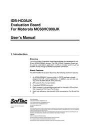
1. YIMOd SSA 1 6 OC SOWB 30001 ano IIS t4 iN 198 o 300 ano S 4 WLI te TNZ ca1d ca1d 191 1014 aan zalda 14 191 5814 ald 1914 191 9914 3ounos 0819 0814 LOL 2914 edd Gan COINA ZOSO 91 2080 gt AS XVW 1950 t os 9 tald SSA z soul LOL How qi YO 81559 802. UNREGEUDD er POWER POWER SUPPLY MC68HC908JK DEMO BOARD The IDB HC08JK Demo Board Supported Devices The IDB HCO08JK Evaluation Board supports the following devices MC68HC908JK1 MC68HC908JK3 And any future MC68HC908JK family pin to pin compatible device Recommended Reading Motorola MCU CD ROM or individual datasheet Motorola CPU08 Central Processor Unit Reference Manual inDART HCO08 User s Manual Sof lec MICROSYSTEMS Page 2 IDB HCO8JK User s Manual 2 Getting Started Overview The IDB HCO8JK Evaluation Board may be used as a standalone application or with a MONO08 based emulator programmer host mode Standalone Mode The IDB HC08JK Evaluation Board comes with the microcontroller pre programmed with a sample application When working in standalone mode the sample application configures the A D peripheral to convert on the A D channel connected to the potentiometer and displays the results on the LEDs In order for the IDB HCO8JK Evaluation Board to work in standalone mode the MONOS connector s pins must be jumpered as show below factory setting J2 1 15 16 MONDOS Connector Jumpered for Standalone Mode Operation Additionally you must verify that the board s other jumpers are set correctly Make sure that both the OSC1
3. J6 and OSC2 J7 jumpers select the INT position This is needed to enable the on board 16 MHz crystal oscillator Make sure that all of the LED ENABLE jumpers J10 and the POTENTIOMETER ENABLE jumper J9 are inserted Make sure that the pre programmed sample device is in the appropriate socket on the board Finally power up the board The IDB HCO8JK Evaluation Board can be powered either via the UNREG VDD connector J3 or the REG VDD connector J4 The UNREG VDD connector accepts 9 12 V DC 200 mA wall plug in power supply with a 2 1 mm pin and sleeve plug with positive in the center and sleeve as ground When powering the board through this connector make sure the VDD SOURCE connector J11 selects the UNREG Position The UNREG VDD voltage is internally regulated to 5 V DC The REG VDD connector accepts 5 V DC max When powering the board through this connector make sure the VDD SOURCE connector J11 selects the REG Position The REG VDD voltage directly powers the microcontroller and the rest of the board Sof lec MICROSYSTEMS Page 3 IDB HCO8JK User s Manual Upon powering up the board the green POWER LED turns on By rotating the potentiometer you affect the results of the A D conversion and the value of each conversion is displayed in a linear bar fashion on the LEDs Host Mode The IDB HCO8JK Evaluation Board can
4. be used in conjunction with a MONDOS8 based emulator programmer such a SofTec Microsystems inDART HCOS8 In Circuit Debugger Programmer or a Motorola development tool If you use the evaluation board with SofTec Microsystems inDART HC08 a sample application similar to that described in the previous section can be executed in Host mode where the program execution is controlled by the host PC You can use the PC additionally to debug the application by for example execute the program step by step and watching how the microcontroller registers vary by using the Metrowerks CodeWarrior HC08 IDE provided with inDART HCO8 The example is available both in Assembly and in C language Please refer to the inDART HCO8 user s manual for a step by step tutorial In order to work with an emulator programmer the jumpers in the MONO8 connector must be removed and the MONOS cable of the emulator programmer must be connected to the evaluation board s MONOS connector J1 connector taking care of the proper polarity The J2 connector is not used in this mode 3 MONO8 Connections J1 Connector Pin Name Description RST_OUT Reset signal to target system GND or open drain output reflecting the state of the MCU RST and RST_IN signals GND System ground RST_IN Reset signal from target system GND to Vpp input to control the state of the MCU RST and RST_OUT signals RST MCU reset held at Vpr Vpp depending on the target mi
5. IDB HCO8JK Evaluation Board For Motorola MC68HC908JK User s Manual 1 Introduction Overview The IDB HC08JK Evaluation Board demonstrates the capabilities of the 20 pin MC68HC908JK devices The IDB HCO08JK Evaluation Board can be used as a standalone application or with an emulator system such as inDART HCO8 through a MONO08 compatible connection Board Features The IDB HC08JK Evaluation Board has the following hardware features 1 An MC68HC908JK3 microcontroller in DIP20 package already programmed with a demo application in addition you can also use any of the MC68HC908JK family devices 2 ZIF socket for the microcontroller A standard MONOS connector 4 Eight jumpers to connect disconnect each of the eight LEDs to from their respective Port B and Port D pins 5 Eight high efficiency low current LEDs connected to Port B and Port e e SofTec Microsystems ec E mail general information info softecmicro com E mail marketing department marketing softecmicro com MICROSYSTEMS E mail technical support support softecmicro com 1 Web http www softecmicro com Copyright 2002 SofTec Microsystems Important DC00524 SofTec Microsystems reserves the right to make improvements to its products their documentation and software routines without notice Information in this manual is intended to be accurate and reliable However SofTec Microsystems assumes no responsibility for its use n
6. crocontroller out of reset No other target system logic should be tied to this signal TGT_IRQ Interrupt signal from target system GND to Vpp input to control the state of the MCU IRQ signal IRQ MCU interrupt held at Vpp when the TGT_IRQ signal is not asserted None N C None N C TGT_PTBO Port B bit 0 reserved MCU connection unavailable to application PTBO Port B bit 0 8 single wire communication TGT PTB1 Port B bit 1 PTB1 Port B bit 1 held at Vpp during reset TGT PTB2 Port B bit 2 PTB2 Port B bit 2 grounded during reset TGT PTB3 Port B bit 3 PTB3 Port B bit 3 held at ground or Vpp during reset depending on the Frequency Divider parameter see inDART HCO08 User s Manual MONDOS Signals Sof lec MICROSYSTEMS Page 4 TENIA 3894S Z00z 60 L2 eieq 8 8 2000 01 1020421012908 MMM fos SLAdLNO SLNdNI er L 39V3S31NI 80NOIN 2550 ald TOL 281191 1919191 08197191 OuT 191 s ANI 1SH 1814 1NO 15 9819 5814 vald SSA ald l 914 ald
7. or for any infringements of rights of third parties which may result from its use SOFTEC MICROSYSTEMS WILL NOT BE LIABLE FOR DAMAGES RESULTING FROM LOSS OF DATA PROFITS USE OF PRODUCTS OR INCIDENTAL OR CONSEQUENTIAL DAMAGES EVEN IF ADVISED OF THE POSSIBILITY THEREOF Trademarks inDART is a trademark of SofTec Microsystems Microsoft and Windows are trademarks or registered trademarks of Microsoft Corporation PC is a registered trademark of International Business Machines Corporation Other products and company names listed are trademarks or trade names of their respective companies IDB HCO8JK User s Manual 6 A potentiometer together with a jumper to connect disconnect it to from PTD2 7 A push button switch connected to RESET 8 Apush button switch together with a jumper to connect disconnect it to from PTD3 9 A16 MHz crystal oscillator together with two jumpers to connect disconnect it from the microcontrollers OSC1 and OSC2 pins 10 A connector for a 9 12 V 200 mA unregulated power supply and an auxiliary power supply connector for a 5 V max regulated together with a jumper to select the power supply source 11 A connector area to access the I O pins of the microcontroller for expansion prototyping 12 A prototyping area F 3 e m ee jen PROTOTYPE AREA i 1 755 0D 806 mmmmmmmHHHHEHEHHEHHHEEHHHNH UD B E 50 yp 0000000
Download Pdf Manuals

Related Search
SOFTEC IDB HC08JK Evaluation Board For Motorola MC68HC908JK User Manual