ANALOG DEVICES ADR440/ADR441/ADR443/ADR444/ADR445 handbook (1)
Contents
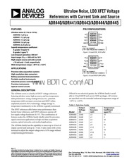
1. 50uV DIV M CH 1 p p 66uV 100 1k 10k 100k 1M FREQUENCY Hz Figure 29 ADR445 10 Hz to 10 kHz Voltage Noise Figure 32 Ripple Rejection Ratio vs Frequency Rev C Page 13 of 20 ADR440 ADR441 ADR443 ADR444 ADR445 THEORY OF OPERATION The ADR44x series of references uses a new reference generation technique known as XFET eXtra implanted junction FET This technique yields a reference with low dropout good thermal hysteresis and exceptionally low noise The core of the XFET reference consists of two junction field effect transistors JFETs one of which has an extra channel implant to raise its pinch off voltage By running the two JFETs at the same drain current the difference in pinch off voltage can be amplified and used to form a highly stable voltage reference The intrinsic reference voltage is around 0 5 V with a negative temperature coefficient of about 120 ppm C This slope is essentially constant to the dielectric constant of silicon and it can be closely compensated for by adding a correction term generated in the same fashion as the proportional to absolute temperature PTAT term used to compensate band gap references The advantage of an XFET reference is its correction term which is approximately 20 times lower and requires less correction than that of a band gap reference Because most of the noise of a band gap reference comes from the temperature compens2. TIME 200us DIV 05428 019 05428 023 Figure 24 ADR441 Load Transient Response Ci 0 1uF Cour 10uF Vin 5VIDIV 5mVIDI Vout 1V DIV S 7 T spon DOS Figure 22 ADR441 Turn On Response Figure 25 ADR441 Load Transient Response TIME 200us DIV 05428 020 05428 022 U CH 1 p p 1 18uV 2mV DIV TIME 1s DIV 05428 021 05428 024 Figure 23 ADR441 Line Transient Response Figure 26 ADR441 0 1 Hz to 10 0 Hz Voltage Noise Rev C Page 12 of 20 ADR440 ADR441 ADR443 ADR444 ADR445 16 14 12 o 50pVIDIV KR 49 Num S n T uad me CH 1 p p D PT M 494V Q8 ul t 6 2 z 4 TIME 1s DIV i S 8 9 2829859877852 see B DE DEVIATION ppm Figure 27 ADR441 10 Hz to 10 kHz Voltage Noise Figure 30 ADR441 Typical Output Voltage Hysteresis a o z a ul n E 2 n 1 E 2 Q L TIME 1s DIV S il 3 10 100 Ak 10k 100k FREQUENCY Hz Figure 28 ADR445 0 1 Hz to 10 0 Hz Voltage Noise Figure 31 Output Impedance vs Frequency
3. 17 Updated Outline Dimensions see 18 8 07 Rev A to Rev B Change to Table 2 Ripple Rejection Ratio Specification 3 Change to Table 3 Ripple Rejection Ratio Specification 4 Change to Table 4 Ripple Rejection Ratio Specification 5 Change to Table 5 Ripple Rejection Ratio Specification 6 Change to Table 6 Ripple Rejection Ratio Specification 7 Theory of Opetation oe e a Re 14 Power Dissipation Considerations sss 14 Basic Voltage Reference Connections sss 14 Noise Performance cero exe A D e ate 14 T rnsOn Times b eR E E 14 Applications Information eene 15 Output Adj stment reete retten bts 15 Bipolar Outputs esee te tetentnnennenne 15 Negative Reference curet eve DA RR i 15 Programmable Voltage Source sees 16 Programmable Current Source sse 16 High Voltage Floating Current Source sss 16 Precision Output Regulator Boosted Reference 17 Outline Dimensions eeen 18 Ordering G der ie PRRERERUCITEES 19 9 06 Rev 0 to Rev A Updated Formate 7 R Ghanges to Features 5 4 H Changes to Pin Configurations Changes to Specifications Section sse 3 Changes to Figure 4 and Figure 5 z9 Inserted Figure 6 and Figure 7 sse 9 Changes to
4. C Figure 13 ADR441 Load Regulation vs Temperature Cn 05428 012 0 40 25 10 5 20 35 50 65 TEMPERATURE C 95 110 N Figure 14 ADR445 Line Regulation vs Temperature DIFFERENTIAL VOLTAGE V LOAD REGULATION ppm mA MINIMUM HEADROOM V 50 Vin 6V 40 ILoap 0mA TO 10mA 30 lLoAp OMA TO 5mA C 05428 013 40 25 10 5 20 35 50 65 110 12 TEMPERATURE C 80 95 Figure 15 ADR445 Load Regulation vs Temperature e 05428 014 LOAD CURRENT mA Figure 16 ADR441 Minimum Input Output Differential Voltage vs Load Current 0 2 0 1 05428 015 20 35 50 65 TEMPERATURE C 125 Figure 17 ADR441 Minimum Headroom vs Temperature ADR440 ADR441 ADR443 ADR444 ADR445 DIFFERENTIAL VOLTAGE V MINIMUM HEADROOM V Rev C Page 11 of 20 5 LOAD CURRENT mA Figure 18 ADR445 Minimum Input Output Differential Voltage vs Load Current TEMPERATURE C Figure 19 ADR445 Minimum Headroom vs Temperature Cin Cour 0 1uF 05428 018 Figure 20 ADR441 Turn On Response 05428 016 0 5 10 Cn 05428 017 ADR440 ADR441 ADR443 ADR444 ADR445 Cin Cour 0 1pF SV DIV 5mVIDI
5. RM 8 ADR444ARMZ REEL7 4 096 i i 5 0713 10 84 ead MSOP R04 i 40 C to 125 C RM 8 ADR444BRZ 4 096 Tp 044 3 8 bhead SOIC IN A 40 Cto 125 C R 8 ADRA444BRZ REEL 7 4 096 1 6 0 04 3 8 Lead SOIC_N 40 C to 125 C R 8 ADR445ARZ 5 000 6 0 12 10 8 Lead SOIC N 40 Cto 125 C R 8 ADR445ARZ REEL7 5 000 6 0 12 10 8 Lead SOIC_N 40 C to 125 C R 8 ADR445ARMZ 5 000 6 0 12 10 8 Lead MSOP R05 40 C to 125 C RM 8 ADR445ARMZ REEL7 5 000 6 0 12 10 8 Lead MSOP R05 40 C to 125 C RM 8 ADR445BRZ 5 000 2 0 04 3 8 Lead SOIC_N 40 C to 125 C R 8 ADR445BRZ REELT 5 000 2 0 04 3 8 Lead SOIC_N 40 C to 125 C R 8 Z RoHS Compliant Part Rev C Page 19 of 20 ADR440 ADR441 ADR443 ADR444 ADR445 NOTES TN DI A Purchase of licensed PC components of Analog Devices or one of its sublicensed Associated Companies conveys a license for the purchaser under the Philips PC Patent Rights to use these components in an C system provided that the system conforms to the PC Standard Specification as defined by Philips 2005 2008 Analog Devices Inc All rights reserved Trademarks and ANALOG registered trademarks are the property of their respective owners pea eco ls DEVICES www analog com Rev C Page 20 of 20
6. 2 048 3 0 15 10 8 Lead SOIC_N 40 C to 125 C R 8 ADR440ARZ REEL7 2 048 3 0 15 10 8 Lead SOIC N 40 Cto 125 C R 8 ADR440ARMZ 2 048 3 0 15 10 8 Lead MSOP R01 40 C to 125 C RM 8 ADR440ARMZ REEL7 2 048 3 0 15 10 8 Lead MSOP R01 40 C to 125 C RM 8 ADR440BRZ 2 048 1 0 05 3 8 Lead SOIC_N 40 C to 125 C R 8 ADRAAOBRZ REEL 7 2 048 1 0 05 3 8 Lead SOIC_N 40 C to 125 C R 8 ADR441ARZ 2 500 3 0 12 10 8 Lead SOIC N 40 C to 125 C R 8 ADR441ARZ REEL7 2 500 3 0 12 10 8 Lead SOIC_N 40 C to 125 C R 8 ADR441ARMZ 2 500 3 0 12 10 8 Lead MSOP RO2 40 C to 125 C RM 8 ADR441ARMZ REEL7 2 500 3 0 12 10 8 Lead MSOP RO2 40 C to 125 C RM 8 ADR441BRZ 2 500 1 0 04 3 8 Lead SOIC_N 40 C to 125 C R 8 ADR441BRZ REEL 7 2 500 1 0 04 3 8 Lead SOIC_N 40 C to 125 C R 8 ADR443ARZ 3 000 4 0 13 10 8 Lead SOIC N 40 Cto 125 C R 8 ADRA443ARZ REEL 7 3 000 4 0 13 10 8 Lead SOIC N 40 C to 125 C R 8 ADR443ARMZ 3 000 4 0 13 10 8 Lead MSOP R03 40 C to 125 C RM 8 ADR443ARMZ REEL7 3 000 4 0 13 10 8 Lead MSOP R03 40 C to 125 C RM 8 ADR443BRZ 3 000 1 2 0 04 3 8 Lead SOIC_N 40 C to 125 C R 8 ADR443BRZ REEL7 3 000 1 2 0 04 3 8 Lead SOIC_N 40 C to 125 C R 8 ADR444ARZ 4 096 5 0 13 10 8 Lead SOIC N 40 C to 125 C R 8 ADR444ARZ REELT 4 096 5 0 13 10 8 Lead SOIC N 40 C to 125 C R 8 ADR444ARMZ 4 096 5 0 123 1 10 8 Lead MSOP R04 40 C to 125 C
7. Figure 15 sse all Changes to Power Dissipation Considerations Section 14 Changes to Figure 35 and Figure 36 sss 15 Changes to Figure 38 and Table 9 sss 16 Updated Outline Dimensions eerte 18 Changes to Ordering Guide sse 19 10 05 Revision 0 Initial Version Rev C Page 2 of 20 ADR440 ADR441 ADR443 ADR444 ADR445 SPECIFICATIONS ADR440 ELECTRICAL CHARACTERISTICS Vin 3 V to 18 V Ta 25 C Cin Cour 0 1 uF unless otherwise noted Table 2 Parameter Symbol Conditions Min Typ Max Unit OUTPUT VOLTAGE Vo A Grade 2 045 2 048 2 051 V B Grade 2 047 2 048 2 049 V INITIAL ACCURACY Voerr A Grade 3 mV 0 15 96 B Grade 1 mV 0 05 96 TEMPERATURE DRIFT TCVo A Grade 40 C lt TA lt 125 C 2 10 ppm C B Grade 40 C lt Ta lt 125 C 1 3 ppm C LINE REGULATION AVo AVin 40 C lt Ta lt 125 C 20 10 20 ppm V LOAD REGULATION AVo Altoap loan 0 MA to 10 mA Vin 3 5 V 40 C lt TA lt 125 C 50 50 ppm mA AVo Alioap loan 0 mA to 5 mA Vin 3 5 V 40 C lt Ta lt 125 C 50 50 ppm mA QUIESCENT CURRENT lin No load 40 C lt Ta lt 125 C 3 3 75 mA VOLTAGE NOISE en p p 0 1 Hz to 10 Hz 1 uV p p VOLTAGE NOISE DENSITY en Y TikHz a 45 nV 4Hz TURN ON SETTLING TIME 1 f i tr L j 10 US LONG TERM STABILITY Vo 1000 hours 50 ppm
8. OUTPUT VOLTAGE HYSTERESIS Vo ys 70 ppm RIPPLE REJECTION RATIO RRR fin 1 kHz 80 dB SHORT CIRCUIT TO GND Isc 27 mA SUPPLY VOLTAGE OPERATING RANGE Vin 3 18 V SUPPLY VOLTAGE HEADROOM Vin Vo 500 mV 1 The long term stability specification is noncumulative The drift in the subsequent 1000 hour period is significantly lower than in the first 1000 hour period Rev C Page 3 of 20 ADR440 ADR441 ADR443 ADR444 ADR445 ADR441 ELECTRICAL CHARACTERISTICS Vin 3 V to 18 V Ta 25 C Cin Cour 0 1 uF unless otherwise noted Table 3 Parameter Symbol Conditions Min Typ Max Unit OUTPUT VOLTAGE Vo A Grade 2 497 2 500 2 503 V B Grade 2 499 2 500 2 501 V INITIAL ACCURACY VotRR A Grade 3 mV 0 12 96 B Grade 1 mV 0 04 96 TEMPERATURE DRIFT TCVo A Grade 40 C lt TA lt 125 C 2 10 ppm C B Grade 40 C lt TA lt 4 125 C 1 3 ppm C LINE REGULATION AVo AVin 40 C lt TA lt 4 125 C 10 20 ppm V LOAD REGULATION AVo Altoap lioap O MA to 10 mA Vn 4 V 40 C lt Ta lt 125 C 50 50 ppm mA AVo Alioao loup 0 mA to 5 mA Vn 4 V 40 C lt TA lt 125 C 50 50 ppm mA QUIESCENT CURRENT lin No load 40 C lt Ta lt 125 C 3 3 75 mA VOLTAGE NOISE en p p 0 1 Hz to 10 Hz 1 2 uV p p VOLTAGE NOISE DENSITY en 1 kHz 48 nV 4Hz TURN ON SETTLING TIME tr 7 10 us LONG TERM STABILITY Vo 1000 hours a 0 ppm OUTPUT VOLTAGE HYSTERESIS UV
9. Voltage Accuracy Coefficient Model V mV ppm C ADR440A 2 048 3 10 ADR440B 2 048 1 3 ADR441A 2 500 3 10 ADR441B 2 500 1 3 ADR443A 3 000 4 10 ADR443B 3 000 1 2 3 ADR444A 4 096 5 10 ADR444B 4 096 1 6 3 ADR445A 5 000 6 10 ADR445B 5 000 2 3 One Technology Way P O Box 9106 Norwood MA 02062 9106 U S A Tel 781 329 4700 www analog com Fax 781 461 3113 2005 2008 Analog Devices Inc All rights reserved ADR440 ADR441 ADR443 ADR444 ADR445 TABLE OF CONTENTS Features Applications Pin Configurations zu ete ttes 1 General Descriptio Mirisni nan EE RRS 1 R vision History cec nui ae ETSR EAE ES 2 Specifications utin et emen xe ee 3 ADR440 Electrical Characteristics sess 3 ADR441 Electrical Characteristics s 4 ADR443 Electrical Characteristics sess 5 ADR444 Electrical Characteristics e 6 ADR445 Electrical Characteristics ses 7 Absolute Maximum Ratings eene 8 Thermal Resistance e 8 ESD Cautions 8 Typical Performance Characteristics sse 9 REVISION HISTORY 3 08 Rev B to Rev C Changes to Table 8 Ab LAY LA 8 8 Change to Figure 11 55 E E 5 E Lust E 10 Changes to Figure 36 15 Changes t Figure 39 eee ete bres 16 Changes to Figure 41
10. la ESD electrostatic discharge sensitive device Charged devices and circuit boards can discharge without detection Although this product features patented or proprietary protection circuitry damage may occur on devices subjected to high energy ESD Therefore proper ESD precautions should be taken to avoid performance degradation or loss of functionality Rev C Page 8 of 20 ADR440 ADR441 ADR443 ADR444 ADR445 TYPICAL PERFORMANCE CHARACTERISTICS Vin 7 V Ta 25 C Cin Cour 0 1 uF unless otherwise noted 2 051 2 050 2 049 2 048 2 047 OUTPUT VOLTAGE V 2 046 2 5020 2 5015 2 5010 2 5005 2 5000 OUTPUT VOLTAGE V 2 4995 2 9995 OUTPUT VOLTAGE V 2 9990 2 9985 2 9980 40 TEMPERATURE C Figure 3 ADR440 Output Voltage vs Temperature 65 TEMPERATURE C Figure 4 ADR441 Output Voltage vs Temperature 25 95 110 12 TEMPERATURE C Figure 5 ADR443 Output Voltage vs Temperature 05428 042 05428 003 05428 004 Rev C Page 9 of 20 4 0980 4 0975 4 0970 E DEVICE 1 4 0965 S 9 4 0960 DEVICE 2 5 DEVICE 3 amp 4 0955 2 o 4 0950 4 0945 g 4 0940 8 40 25 10 5 20 35 50 65
11. loading TY DII C NAD Rev C Page 17 of 20 ADR440 ADR441 ADR443 ADR444 ADR445 OUTLINE DIMENSIONS 5 00 0 1968 4 80 0 1890 4 00 0 1574 6 20 0 2441 3 80 0 1497 5 80 0 2284 Hua 2 27 0 05 0 50 0 0196 1 27 0 0500 50 0 BSC 1 75 0 0688 M 0 25 0 0099 0 25 0 0098 1 35 0 0532 a 0 10 0 0040 Y vy coPLANARITY X 0 51 0 0201 y gt e A0 631 0 0122 bias 0 0008 1 27 0 0500 SEATING 0 29 0 0098 0 40 0 0157 PLANE 0 17 0 0067 COMPLIANT TO JEDEC STANDARDS MS 012 AA CONTROLLING DIMENSIONS ARE IN MILLIMETERS INCH DIMENSIONS IN PARENTHESES ARE ROUNDED OFF MILLIMETER EQUIVALENTS FOR REFERENCE ONLY AND ARE NOT APPROPRIATE FOR USE IN DESIGN Figure 42 8 Lead Standard Small Outline Package SOIC_N Narrow Body R 8 Dimensions shown in millimeters and inches 012407 A 0 95 0 85 1 10 MAX 0 75 Ta CST a gt 0 80 0 15 038 o23 1 f gt 0 60 0 00 0 22 0 08 0 40 COPLANARITY SEATING 0 10 PLANE COMPLIANT TO JEDEC STANDARDS MO 187 AA Figure 43 8 Lead Mini Small Outline Package MSOP RM 8 Dimensions show in millimeters Rev C Page 18 of 20 ADR440 ADR441 ADR443 ADR444 ADR445 ORDERING GUIDE Initial Temperature Output Accuracy Coefficient Package Temperature Package Model Voltage V mV 96 Package ppm C Description Branding Range Option ADR440ARZ
12. the input can help with line voltage transient performance ADR440 ADR441 EH ADR443 1 nc ADR444 ADR445 TOP VIEW Not t Scale B TRIM NOTES s T NC Z N CONNECT 2 TP TEST PIN DO NOT CONNECT 05428 034 Figure 34 Basic Voltage Reference Configuration NOISE PERFORMANCE The noise generated by the ADR44x family of references is typically less than 1 4 uV p p over the 0 1 Hz to 10 0 Hz band for ADR440 ADR441 and ADR443 Figure 26 shows the 0 1 Hz to 10 Hz noise of the ADR441 which is only 1 2 uV p p The noise measurement is made with a band pass filter composed of a 2 pole high pass filter with a corner frequency at 0 1 Hz and a 2 pole low pass filter with a corner frequency at 10 0 Hz TURN ON TIME Upon application of power cold start the time required for the output voltage to reach its final value within a specified error band is defined as the turn on settling time Two compo nents normally associated with this are the time for the active circuits to settle and the time for the thermal gradients on the chip to stabilize Figure 20 and Figure 21 show the turn on and turn off settling times for the ADR441 Rev C Page 14 of 20 ADR440 ADR441 ADR443 ADR444 ADR445 APPLICATIONS INFORMATION OUTPUT ADJUSTMENT The ADR44x family features a TRIM pin that allows the user to adjust the output voltage of the part over a limited range This allows errors from the reference and overall system errors
13. 80 95 110 125 TEMPERATURE C Figure 6 ADR444 Output Voltage vs Temperature 5 006 5 004 S 5002 SL 5 000 K N n 5 4 998 o 4 996 3 4 994 8 40 20 0 20 40 60 80 100 120 TEMPERATURE C Figure 7 ADR445 Output Voltage vs Temperature 4 0 35 lt 3 125 C z WW E ATITA x 30 ee Sea E H Ha a A a 40 C a 25 2 0 8 4 6 8 10 12 14 16 18 INPUT VOLTAGE V Figure 8 ADR441 Supply Current vs Input Voltage ADR440 ADR441 ADR443 ADR444 ADR445 SUPPLY CURRENT mA SUPPLY CURRENT mA SUPPLY CURRENT mA 4 0 3 5 3 0 2 5 2 0 40 3 5 3 4 3 25 3 15 3 05 2 95 2 85 2 75 40 05428 007 25 10 5 20 65 TEMPERATURE C Figure 9 ADR441 Supply Current vs Temperature 125 C 25 C t 05428 008 7 3 9 3 11 3 13 3 INPUT VOLTAGE V 15 3 Figure 10 ADR445 Supply Current vs Input Voltage 05428 009 25 10 5 20 35 50 65 TEMPERATURE C 80 95 110 12 Figure 11 ADR445 Supply Current vs Temperature Rev C Page 10 of 20 LINE REGULATION ppm V LOAD REGULATION ppm mA LINE REGULATION ppm V C 05428 010 65 TEMPERATURE C 110 12 Figure 12 ADR441 Line Regulation vs Temperature lLoAp OMA TO 10mA 05428011 30 40 25 12 TEMPERATURE
14. ANALOG Ultralow Noise LDO XFET Voltage DEVICES References with Current Sink and Source ADR440 ADR441 ADR443 ADR444 ADR445 FEATURES Ultralow noise 0 1 Hz to 10 Hz ADR440 1 HV p p ADR441 1 2 pV p p ADR443 1 4 pV p p ADR444 1 8 pV p p ADR445 2 25 uV p p Superb temperature coefficient A grade 10 ppm C B grade 3 ppm C Low dropout operation 500 mV Input range Vout 500 mV to 18V High output source and sink current 10 mA and 5 mA respectively Wide temperature range 40 C to 125 C APPLICATIONS Precision data acquisition systems High resolution data converters Battery powered instrumentation Portable medical instruments 1 Industrial process control UU i Precision instruments t Optical control circuits GENERAL DESCRIPTION The ADR44x series is a family of XFET voltage references featuring ultralow noise high accuracy and low temperature drift performance Using Analog Devices Inc patented temperature drift curvature correction and XFET eXtra implanted junction FET technology voltage change vs temperature nonlinearity in the ADR44x is greatly minimized The XFET references offer better noise performance than buried Zener references and XFET references operate off low supply voltage headroom 0 5 V This combination of features makes the ADR44x family ideally suited for precision signal conversion applications in high end data acquisition systems optical networks and medical appli
15. E REJECTION RATIO RRR fin 1 kHz 80 dB SHORT CIRCUIT TO GND Isc 27 mA SUPPLY VOLTAGE OPERATING RANGE Vin 3 5 18 V SUPPLY VOLTAGE HEADROOM Vin Vo 500 mV 1 The long term stability specification is noncumulative The drift in the subsequent 1000 hour period is significantly lower than in the first 1000 hour period Rev C Page 5 of 20 ADR440 ADR441 ADR443 ADR444 ADR445 ADR444 ELECTRICAL CHARACTERISTICS Vin 4 6 V to 18 V Ta 25 C Cin Cour 0 1 uF unless otherwise noted Table 5 Parameter Symbol Conditions Min Typ Max Unit OUTPUT VOLTAGE Vo A Grade 4 091 4 096 4 101 V B Grade 4 0944 4 096 4 0976 V INITIAL ACCURACY VotRR A Grade 5 mV 0 13 96 B Grade 1 6 mV 0 04 96 TEMPERATURE DRIFT TCVo A Grade 40 C lt Ta lt 125 C 2 10 ppm C B Grade 40 C lt Ta lt 125 C 1 3 ppm C LINE REGULATION AVo AVin 40 C lt TA lt 125 C 10 20 ppm V LOAD REGULATION AVo Alioap lioap 0 mA to 10 mA Vin 5 5 V 40 C lt TA lt 125 C 50 50 ppm mA AVo Altoap loan 0 mA to 5 mA Vn 5 5 V 40 C lt Ta lt 125 C 50 50 ppm mA QUIESCENT CURRENT lin No load 40 C lt Ta lt 125 C 3 3 75 mA VOLTAGE NOISE en p p 0 1 Hz to 10 Hz 1 8 uV p p VOLTAGE NOISE DENSITY en 1 kHz 78 6 nV 4Hz TURN ON SETTLING TIME tr 7 10 us LONG TERM STABILITY Mo 1000 hours s E ppm OUTPUT VOLTAGE HYSTERESIS t Veus AO ppm RIPP
16. E REJECTION RATIO RRR fin 1 kHz 80 dB SHORT CIRCUIT TO GND Isc 27 mA SUPPLY VOLTAGE OPERATING RANGE Vin 5 5 18 V SUPPLY VOLTAGE HEADROOM Vin Vo 500 mV 1 The long term stability specification is noncumulative The drift in the subsequent 1000 hour period is significantly lower than in the first 1000 hour period Rev C Page 7 of 20 ADR440 ADR441 ADR443 ADR444 ADR445 ABSOLUTE MAXIMUM RATINGS Ta 25 C unless otherwise noted Table 7 Parameter Rating Supply Voltage 20V Output Short Circuit Duration to GND Indefinite Storage Temperature Range 65 C to 125 C Operating Temperature Range 40 C to 125 C Junction Temperature Range 65 C to 150 C Lead Temperature Soldering 60 sec 300 C Stresses above those listed under Absolute Maximum Ratings may cause permanent damage to the device This is a stress rating only functional operation of the device at these or any other conditions above those indicated in the operational section of this specification is not implied Exposure to absolute maximum rating conditions for extended periods may affect device reliability UM THERMAL RESISTANCE Oya is specified for the worst case conditions that is a device soldered in a circuit board for surface mount packages Table 8 Thermal Resistance Package Type Osa Osc Unit 8 Lead SOIC R Suffix 130 43 C W 8 Lead MSOP RM Suffix 1325 43 9 C W ESD CAUTION
17. LE REJECTION RATIO RRR fin 1 kHz 80 dB SHORT CIRCUIT TO GND Isc 27 mA SUPPLY VOLTAGE OPERATING RANGE Vin 4 6 18 V SUPPLY VOLTAGE HEADROOM Vin Vo 500 mV 1 The long term stability specification is noncumulative The drift in the subsequent 1000 hour period is significantly lower than in the first 1000 hour period Rev C Page 6 of 20 ADR440 ADR441 ADR443 ADR444 ADR445 ADR445 ELECTRICAL CHARACTERISTICS Vin 5 5 V to 18 V Ta 25 C Cin Cour 0 1 uF unless otherwise noted Table 6 Parameter Symbol Conditions Min Typ Max Unit OUTPUT VOLTAGE Vo A Grade 4 994 5 000 5 006 V B Grade 4 998 5 000 5 002 V INITIAL ACCURACY VotRR A Grade 6 mV 0 12 96 B Grade 2 mV 0 04 96 TEMPERATURE DRIFT TCVo A Grade 40 C lt TA lt 125 C 2 10 ppm C B Grade 40 C lt Ta lt 125 C 1 3 ppm C LINE REGULATION AVo AVin 40 C lt Ta lt 125 C 10 20 ppm V LOAD REGULATION AVo Altoap loan 0 mA to 10 mA Vin 6 5 V 40 C lt Ta lt 125 C 50 50 ppm mA AVo Alioao loup 0 mA to 5 mA Vin 6 5 V 40 C lt TA lt 125 C 50 50 ppm mA QUIESCENT CURRENT lin No load 40 C lt Ta lt 125 C 3 3 75 mA VOLTAGE NOISE en p p 0 1 Hz to 10 Hz 2 25 uV p p VOLTAGE NOISE DENSITY en 1 kHz 90 nV 4Hz TURN ON SETTLING TIME tr S l 10 US LONG TERM STABILITY Vo 1000 hours s i 50 ppm OUTPUT VOLTAGE HYSTERESIS UL V Vous 70 ppm RIPPL
18. Vilars ppm RIPPLE REJECTION RATIO RRR fin 1 kHz 80 dB SHORT CIRCUIT TO GND Isc 27 mA SUPPLY VOLTAGE OPERATING RANGE Vin 3 18 V SUPPLY VOLTAGE HEADROOM Vin Vo 500 mV 1 The long term stability specification is noncumulative The drift in subsequent 1000 hour period is significantly lower than in the first 1000 hour period Rev C Page 4 of 20 ADR440 ADR441 ADR443 ADR444 ADR445 ADR443 ELECTRICAL CHARACTERISTICS Vin 3 5 V to 18 V Ta 25 C Cin Cour 0 1 uF unless otherwise noted Table 4 Parameter Symbol Conditions Min Typ Max Unit OUTPUT VOLTAGE Vo A Grade 2 996 3 000 3 004 V B Grade 2 9988 3 000 3 0012 V INITIAL ACCURACY VotRR A Grade 4 mV 0 13 96 B Grade 1 2 mV 0 04 96 TEMPERATURE DRIFT TCVo A Grade 40 C lt TA lt 125 C 2 10 ppm C B Grade 40 C lt Ta lt 125 C 1 3 ppm C LINE REGULATION AVo AVin 40 C lt TA lt 4 125 C 10 20 ppm V LOAD REGULATION AVo Alioap lioap 0 mA to 10 mA Vn 5 V 40 C lt TA lt 125 C 50 50 ppm mA AVo Altoap lioap 0 mA to 5 mA Vn 5V 40 C lt Ta lt 125 C 50 50 ppm mA QUIESCENT CURRENT lin No load 40 C lt Ta lt 125 C 3 3 75 mA VOLTAGE NOISE en p p 0 1 Hz to 10 Hz 1 4 uV p p VOLTAGE NOISE DENSITY en 1 kHz 57 6 nV 4Hz TURN ON SETTLING TIME tr S 10 US LONG TERM STABILITY 4 Vo 1000 hours 50 ppm OUTPUT VOLTAGE HYSTERESIS B Vows A 70 ppm RIPPL
19. ation circuitry the XFET results in much lower noise Figure 33 shows the basic topology of the ADR44x series The temperature correction term is provided by a current source with a value designed to be proportional to the absolute temperature The general equation is i l Vour G AV RI x Iprar i 1 where G is the gain of the reciprocal of the divider ratio AV is the difference in pinch off voltage between the two JFETs Ivrar is the positive temperature coefficient correction current ADR44x devices are created by on chip adjustment of R2 and R3 to achieve the different voltage options at the reference output O Vin EXTRA CHANNEL IMPLANT Vout G AVp R1 x Iprar GND 05428 033 Figure 33 Simplified Schematic Device POWER DISSIPATION CONSIDERATIONS The ADR44x family of references is guaranteed to deliver load currents to 10 mA with an input voltage that ranges from 3 V to 18 V When these devices are used in applications at higher currents use the following equation to account for the temperature effects of increases in power dissipation T Pp x Oja Ta 2 where T and Ta are the junction and ambient temperatures respectively Ppis the device power dissipation z is the device package thermal resistance BASIC VOLTAGE REFERENCE CONNECTIONS The ADR44x family requires a 0 1 uF capacitor on the input and the output for stability Although not required for operation a 10 uF capacitor at
20. cations The ADR44x family has the capability to source up to 10 mA of output current and sink up to 5 mA It also comes with a trim terminal to adjust the output voltage over a 0 596 range without compromising performance Rev C Information fumished by Analog Devices is believed to be accurate and reliable However no responsibility is assumed by Analog Devices for its use nor for any infringements of patents or other rights of third parties that may result from its use Specifications subject to change without notice No license is granted by implication or otherwise under any patent or patent rights of Analog Devices Trademarks and registered trademarks are the property of their respective owners PIN CONFIGURATIONS U ADR440 TPL apRaat E Vin 2 ADR443 NC ADR444 NC 3 ADR445 LS Your TOP VIEW GND 4 Not to Scale NOTES 1 NC NO CONNECT 2 TP TEST PIN DO NOT CONNECT Figure 1 8 Lead SOIC N R Suffix 05428 001 ADR440 LU ADRA441 H ADR443 ISJ ADRA444l TOP VIEW GND 4 Not to Scale 5 TRIM NOTES 1 NC NO CONNECT 2 TP TEST PIN DO NOT CONNECT Figure 2 8 Lead MSOP RM Suffix NAL 05428 002 Offered in two electrical grades the ADR44x family is avail able in 8 lead MSOP and narrow SOIC packages All versions are specified over the extended industrial temperature range of 40 C to 125 C Table 1 Selection Guide Output Initial Temperature
21. rammable current source using a setup similar to the programmable voltage source as shown in Figure 39 The constant voltage on the gate of the transistor sets the current through the load Varying the voltage on the gate changes the current This circuit does not require a dual digital potentiometer Vcc O 0 1pF 1 Vin ADR440 ADR441 ADR443 ADR444 ADR445 05428 039 Figure 39 Programmable Current Source HIGH VOLTAGE FLOATING CURRENT SOURCE Use the circuit in Figure 40 to generate a floating current source with nmrriurahself heating This P ue configuration can operate omhigh supply voltages determined by the breakdown voltage of the N channel JFET Vs T SST111 VISHAY ViN ADR440 ADR441 ADR443 ADR444 ADR445 2N3904 Figure 40 Floating Current Source Rev C Page 16 of 20 ADR440 ADR441 ADR443 ADR444 ADR445 PRECISION OUTPUT REGULATOR BOOSTED REFERENCE ViN ViN ADR440 ADR441 ADR443 ADR444 ADR445 05428 041 Figure 41 Boosted Output Reference Higher current drive capability can be obtained without sacrificing accuracy by using the circuit in Figure 41 The operational amplifier regulates the MOSFET turn on forcing Vo to equal the Vrer Current is then drawn from Vm allowing increased current drive capability The circuit allows a 50 mA load if higher current drive is required use a larger MOSFET For fast transient response add a buffer at Vo to aid with capacitive
22. shows how to connect the ADR44x and a standard operational amplifier such as the OP 1177 to provide negative voltage This configuration provides two main advantages First it only requires two devices therefore it does not require excessive board space Second and more importantly it does not require any external resistors This means the performance ofthis circuit does not rely choosing low temperature coefficient resistors o Mss Vpp Q Vin ADR440 ADR441 ADR443 ADR444 ADR445 05428 037 O VDD Figure 37 ADR44x Negative Reference Vovr is at virtual ground and the negative reference is taken directly from the output of the operational amplifier If the negative supply voltage is close to the reference output the operational amplifier must be dual supply and have low offset and rail to rail capability Rev C Page 15 of 20 ADR440 ADR441 ADR443 ADR444 ADR445 PROGRAMMABLE VOLTAGE SOURCE To obtain different voltages than those offered by the ADR44x some extra components are needed In Figure 38 two potenti ometers are used to set the desired voltage and the buffering amplifier provides current drive The potentiometer connected between Vour and GND with its wiper connected to the noninverting input of the operational amplifier takes care of coarse trim The second potentiometer with its wiper connected to the trim terminal of the ADR44x is used for fine adjustment Resolution depends on the end
23. to be trimmed out by connecting a potentiometer between the output and the ground with the wiper connected to the TRIM pin Figure 35 shows the optimal trim configuration R1 allows fine adjustment of the output and is not always required R should be sufficiently large so that the maximum output current from the ADR44x is not exceeded 0 1yF Vin Vour O Vo 0 5 ADR440 ADR441 ADR443 ADR444 ADR445 05428 035 Figure 35 ADR44x Trim Function LS 1 Using the trim function has a negli gible effect on the temperature performance of the ADR44x However all fesist fs need to be low temperature coefficient resistors or errors may occur BIPOLAR OUTPUTS By connecting the output of the ADR44x to the inverting ter minal of an operational amplifier it is possible to obtain both positive and negative reference voltages Care must be taken when choosing Resistors R1 and R2 see Figure 36 These resistors must be matched as closely as possible to ensure mini mal differences between the negative and positive outputs In addition care must be taken to ensure performance over temperature Use low temperature coefficient resistors if the circuit is used over temperature otherwise differences exist between the two outputs Vpp O Vin ADR440 ADR441 ADR443 ADR444 HWE ADR445 O 5V R1 R2 10kO 10kQ 05428 036 O 10V Figure 36 ADR44x Bipolar Outputs NEGATIVE REFERENCE Figure 37
24. to end resistance value and the resolution of the selected potentiometer Vpp e ViN ADR440 ADR441 ADR443 ADR444 ADR445 Vout TT GND O ADJ VREF R1 R2 10kQ 10kQ 05428 038 Figure 38 Programmable Voltage Source For a completely programmable solution replace the two potentiometers in Figure 38 with one Analog Devices dual digital potentiometer offered with ilhet n SPI or n G interface These interfaces set the position of the wiper on both potentiometers and allow the output voltage to be set Table 9 lists compatible Analog Devices digital potentiometers Table 9 Digital Potentiometer Parts No of No of Vop Part No Channels Positions ITF R kO V AD5251 2 00 64 00 PC 1 10 50 100 5 5 AD5207 2 00 256 00 SPI 10 50 100 5 5 AD5242 2 00 256 00 PC 10 100 1M 5 5 AD5262 2 00 256 00 SPI 20 50 200 15 AD5282 2 00 256 00 PC 20 50 100 15 AD5252 2 00 256 00 PC 1 10 50 100 5 5 AD5232 2 00 256 00 SPI 10 50 100 5 5 AD5235 2 00 1024 00 SPI 25 250 5 5 ADN2850 2 00 1024 00 SPI 25 250 5 5 1 Can also use a negative supply Adding a negative supply to the operational amplifier allows the user to produce a negative programmable reference by connecting the reference output to the inverting terminal of the operational amplifier Choose feedback resistors to minimize errors over temperature PROGRAMMABLE CURRENT SOURCE It is possible to build a prog
Download Pdf Manuals

Related Search
ANALOG DEVICES ADR440/ADR441/ADR443/ADR444/ADR445 handbook (1)